Supercharge Your Innovation With Domain-Expert AI Agents!

Hollow shutter glass control mechanism convenient to operate

A louver glass and control mechanism technology, applied in the direction of power control mechanism, wing fan control mechanism, building components, etc., can solve the problems of heavy workload and slow maintenance work, and achieve convenient operation, convenient centralized processing, and maintenance efficiency. Effect

Pending Publication Date: 2022-07-22
聚宝盆(苏州)特种玻璃股份有限公司
View PDF0 Cites 0 Cited by
  • Summary
  • Abstract
  • Description
  • Claims
  • Application Information

AI Technical Summary

Problems solved by technology

[0005] The invention provides a hollow louver control mechanism with convenient operation, which solves the problems that the existing ventilated louver needs to be manually maintained regularly, the maintenance work is slow, and the workload is heavy.

Method used


Image

  • Hollow shutter glass control mechanism convenient to operate
  • Hollow shutter glass control mechanism convenient to operate
  • Hollow shutter glass control mechanism convenient to operate

Examples


no. 1 example

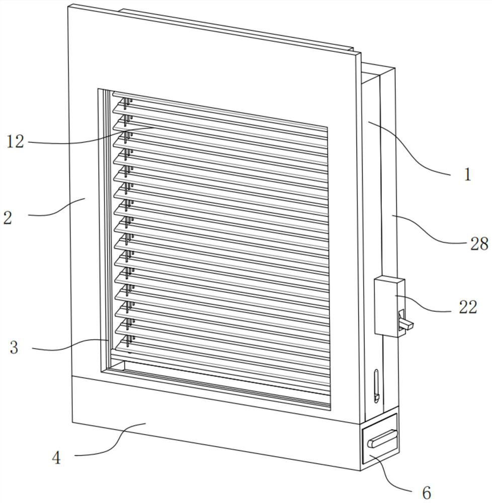
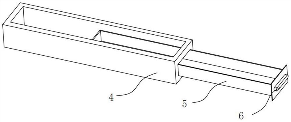
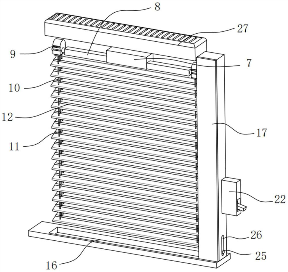
[0027] Please refer to figure 1 , figure 2 , image 3 , Figure 4 ,in, figure 1 It is a schematic structural diagram of the first embodiment of a control mechanism for hollow louver glass with convenient operation provided by the present invention; figure 2 A schematic structural diagram of a collection box of a control mechanism for hollow louver glass provided by the present invention; image 3 A schematic diagram of the internal structure of a control mechanism for hollow louver glass with convenient operation provided by the present invention; Figure 4 It is a schematic structural diagram of the inside of the shaking box of the control mechanism for hollow louver glass provided by the present invention. An easy-to-operate hollow shutter glass control mechanism includes: a main frame 1;

[0028] Panel 2, the panel 2 is fixedly installed on the front side surface of the main frame 1, and the interior of the panel 2 is provided with a glass slot 3 for installing the ...

no. 2 example

[0042] see Figure 5 , Figure 5 It is a schematic structural diagram of the second embodiment of a control mechanism for hollow louver glass with convenient operation provided by the present invention. Based on an easy-to-operate hollow shutter glass control mechanism provided in the first embodiment of the present application, the second embodiment of the present application proposes another easy-to-operate hollow shutter glass control mechanism. The second embodiment is only a preferred mode of the first embodiment, and the implementation of the second embodiment will not affect the independent implementation of the first embodiment.

[0043] Specifically, the easy-to-operate hollow shutter glass control mechanism provided by the second embodiment of the present application is different in that, in the easy-to-operate hollow shutter glass control mechanism, the outer side of the installation sleeve 28 is fixedly installed with Shock pad 29.

[0044] The shock-absorbing p...


PUM


Abstract

The hollow shutter glass control mechanism convenient to operate comprises a main frame, a panel is fixedly installed on the front side surface of the main frame, a glass clamping groove used for installing glass is formed in the panel, a servo motor is fixedly installed in the main frame, and the servo motor can control a flat pull rope to pull a shutter plate to adjust the angle. The winder can control the lifting rope to rotate upwards to be stored so as to lift the shutter plate, and a mounting sleeve plate is fixedly mounted on the surface of the rear side of the main frame and used for fixed mounting. According to the hollow louver glass control mechanism convenient to operate, air blowing and dust removal are conducted on louver boards through a draught fan, a servo motor box is matched to control a rotating shaft head to drive a shaking gear head to rotate and control an outwards-extending convex plate to shake side plates up and down, and under the vertical reset action of a spring ring and a movable plate, dust removal work can be effectively conducted; and collection is carried out through a collection box at the bottom, follow-up centralized treatment is facilitated, and the efficiency is improved.

Description

technical field [0001] The invention relates to the technical field of louver glass, in particular to a control mechanism for hollow louver glass with convenient operation. Background technique [0002] Hollow louver is a traditional sunshade product. Generally, it is artificially used in the interior of the hollow glass to control the blinds in the hollow glass. Relying on advanced technology, the blinds are installed in the hollow glass as a whole, and the magnetic force is used to control the inside of the hollow glass. The blinds can be easily raised or turned 180 degrees. The product not only saves the use of space, but also achieves the purpose of shading, and also has the functions of heat preservation and anti-noise, and at the same time gives the building and interior a novel vision. [0003] Whether in summer or winter, the angle of the blinds can be adjusted to achieve shading or lighting and heating, so that the energy consumption of the air conditioner can be g...

Claims


Application Information

Patent Timeline
IPC IPC(8): E06B7/086E06B9/28E05F15/603
CPCE05F15/603E06B7/086E06B9/28
Inventor 曹旭
Owner 聚宝盆(苏州)特种玻璃股份有限公司
Features
  • R&D
  • Intellectual Property
  • Life Sciences
  • Materials
  • Tech Scout
  • Unparalleled Data Quality
  • Higher Quality Content
  • 60% Fewer Hallucinations
Learn More