
Abnormality detection device, load driving device, abnormality detection method, and storage medium

An anomaly detection and anomaly technology, applied in the direction of measuring devices, electric heating devices, emergency protection detection, etc., can solve problems such as the complexity of the drive circuit structure, and achieve the effect of a simple structure

Pending Publication Date: 2022-07-22
TOYOTA JIDOSHA KK
View PDF1 Cites 0 Cited by
  • Summary
  • Abstract
  • Description
  • Claims
  • Application Information

AI Technical Summary

Problems solved by technology

Therefore, in the technology described in Japanese Patent Application Laid-Open No. 2020-137089, the structure for detecting abnormality of the drive circuit becomes complicated.

Method used


Image

  • Abnormality detection device, load driving device, abnormality detection method, and storage medium
  • Abnormality detection device, load driving device, abnormality detection method, and storage medium
  • Abnormality detection device, load driving device, abnormality detection method, and storage medium

Examples


no. 1 approach 〕

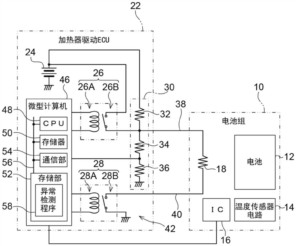
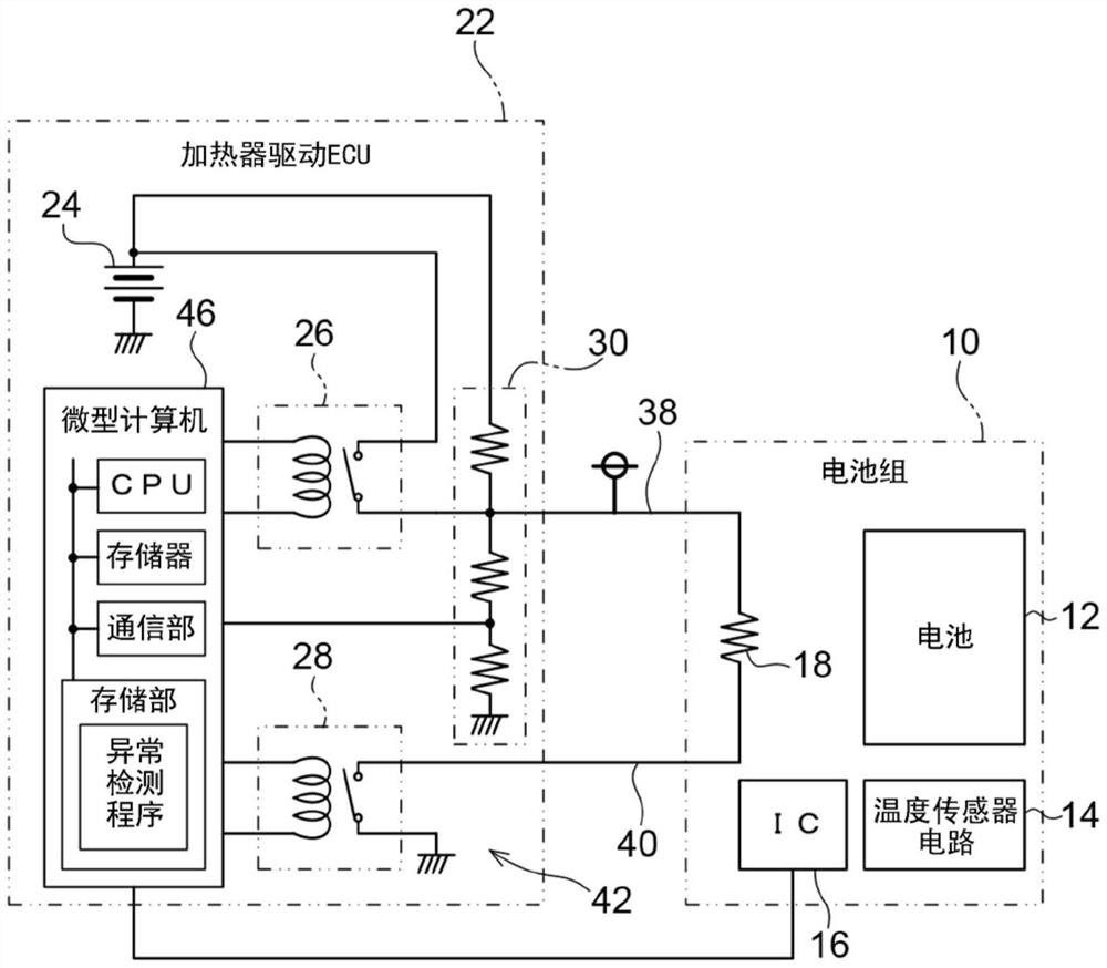
[0057] exist figure 1 In the figure, the battery pack 10 and the heater drive ECU 22 that drives the heater 18 built in the battery pack 10 are shown. The battery pack 10 and the heater drive ECU 22 are mounted on a vehicle (not shown), and are connected by a high-side connection wire 38 and a low-side connection wire 40 .

[0058] The battery pack 10 includes a battery 12 , a temperature sensor circuit 14 that detects the temperature of the battery 12 , and an IC (Integrated Circuit) 16 that transmits the temperature of the battery 12 detected by the temperature sensor circuit 14 to the heater drive ECU 22 . and a heater 18 that heats the battery 12 when energized. Heater 18 is one example of an electrical load in this disclosure. The battery 12 of the battery pack 10 functions as, for example, a backup power source of an auxiliary battery (not shown) mounted on a vehicle.

[0059] Further, the heater drive ECU 22 includes a power supply unit 24, a first relay 26 provided ...

no. 2 approach 〕

[0120] Next, a second embodiment of the present disclosure will be described. In addition, since the second embodiment has the same structure as the first embodiment, the same reference numerals are attached to the respective parts and the description of the structure is omitted. Hereinafter, the functions of the second embodiment are different from those of the first embodiment. section is explained.

[0121] In the first embodiment, the control unit 62 switches the first relay 26 and the second relay 28 to three states of “both relays off”, “low-side relay on”, and “both relays on”. method is explained. In the second embodiment, in addition to the above-mentioned three states, the control unit 62 turns the first relay 26 and the second relay 28 into an ON state and turns the second relay 28 into an OFF state. state of "High-Side Relay On" (refer to Figure 18 : an example of the fourth state in the present disclosure) to switch.

[0122] When the control unit 62 switches...


PUM


Abstract

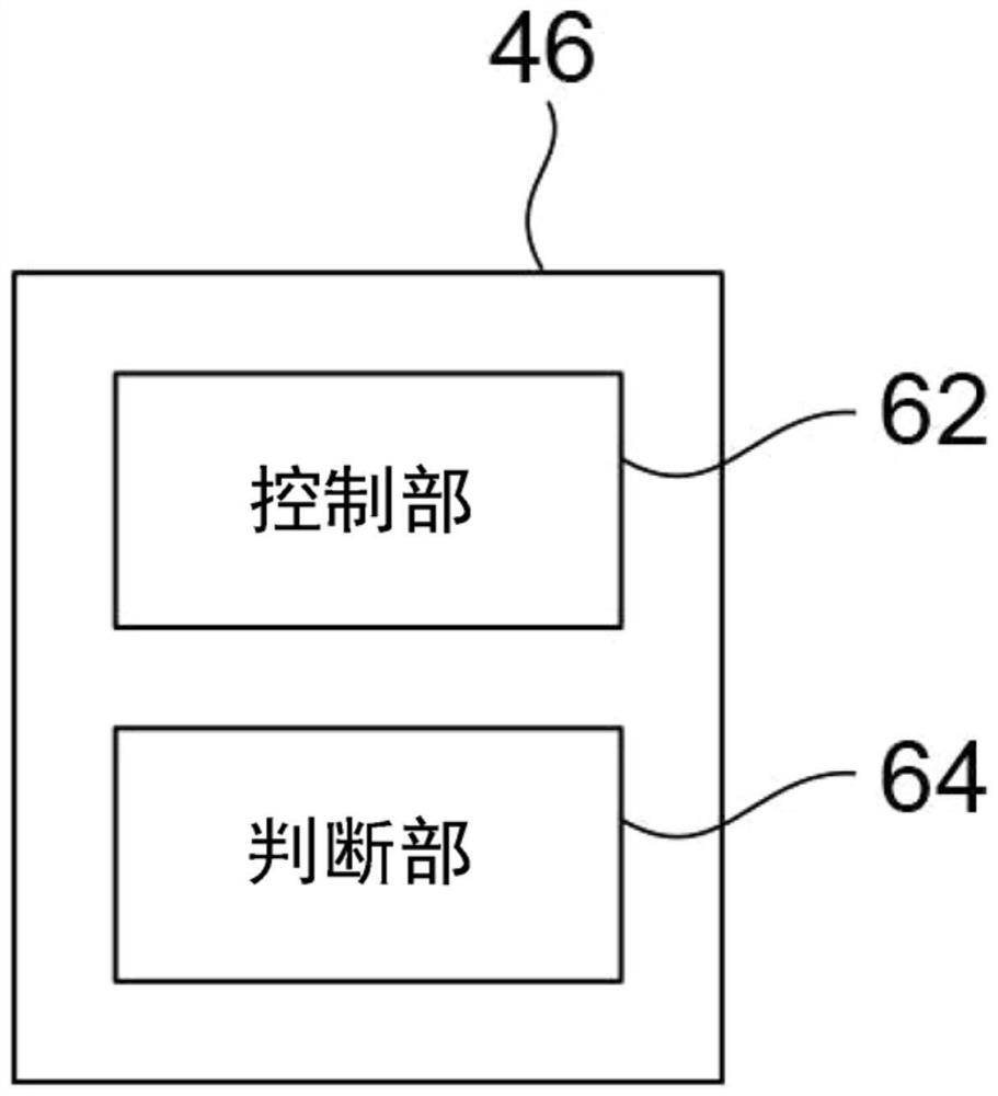
The present disclosure provides an abnormality detection device, a load driving device, an abnormality detection method, and a storage medium that detect an abnormality in a driving circuit with a simple configuration. The microcomputer functions as a control unit and a determination unit. In a drive circuit including a first relay provided between the heater and the power supply unit and a second relay provided between the heater and the ground, the control unit controls the first relay to be in an on state in which the heater and the power supply unit are connected or in an off state in which the heater and the power supply unit are cut off. And the second relay is controlled to be in a conduction state for connecting the heater and the ground wire or a disconnection state for cutting off the heater and the ground wire. The determination unit determines an abnormality in the drive circuit on the basis of the ON / OFF state of the first relay and the second relay, and a determination voltage detected by a voltage sensor circuit that detects a determination voltage between the first relay and the heater.

Description

technical field [0001] The present disclosure relates to an abnormality detection device, a load driving device, an abnormality detection method, and a storage medium storing an abnormality detection program. Background technique [0002] The control device described in Japanese Patent Laid-Open No. 2020-137089 includes: a high-side wiring connecting between the heater and a power supply, a low-side wiring connecting the heater and the ground, and a wiring connected to the heater. Induction wiring on the heating electrode, and a fault detection unit for detecting faults in each wiring connected to the heater. Further, the failure detection unit determines the type of the failure and the location where the failure occurs based on the high-side voltage, low-side voltage, induced voltage, high-side current, and low-side current, respectively. [0003] In the technique described in Japanese Patent Application Laid-Open No. 2020-137089, when detecting an abnormality of the drive...

Claims


Application Information

Patent Timeline
Patent Type & Authority Applications(China)
IPC IPC(8): G01R31/00G01R31/327
CPCG01R31/00G01R31/327H05B1/0202H02H1/0007H02H3/16H05B1/0236
Inventor 驯松智洋
Owner TOYOTA JIDOSHA KK
Learn More