Concrete filled steel tubular column with wolf tooth core column

A technology of concrete-filled steel tube columns and spike cores, which is applied in the direction of columns, pillars, pier columns, etc., can solve the problems of limited use space, increased structural self-weight, and large cross-sectional size, so as to reduce the cross-sectional size and material consumption, Improve the bearing capacity and reduce the effect of plastic deformation

Pending Publication Date: 2022-07-29
GUANGZHOU UNIVERSITY
View PDF0 Cites 0 Cited by
  • Summary
  • Abstract
  • Description
  • Claims
  • Application Information

AI Technical Summary

Problems solved by technology

[0004] The object of the present invention is to provide a steel pipe concrete column with a spiked core column in order to solve the problems in the prior art that the load-bearing column of the building structure has a large cross-sectiona

Method used


Image

  • Concrete filled steel tubular column with wolf tooth core column
  • Concrete filled steel tubular column with wolf tooth core column
  • Concrete filled steel tubular column with wolf tooth core column

Examples


Example Embodiment

[0027] Example 1

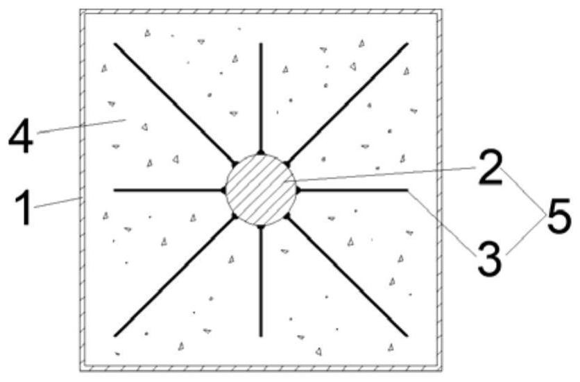
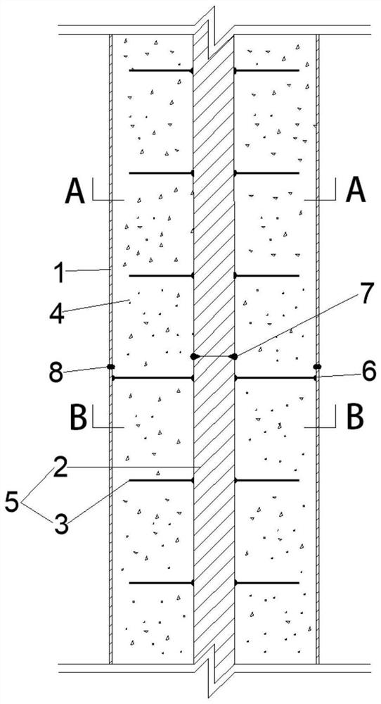
[0028] see figure 1 , The concrete-filled steel tubular column with a wolf-tooth core column provided by the embodiment of the present invention includes an outer steel pipe 1 , a concrete 4 and a wolf-tooth core column 5 . The outer steel pipe is a square steel pipe, and high-strength concrete is filled between the outer steel pipe and the wolf tooth core column. In other examples, the outer steel pipe can be circular or other shapes, and other types of concrete can also be used for the concrete, which are not listed here. List statements. The wolf tooth core column 5 includes a steel column 2 and eight ribbed steel bars 3. The geometric center of the steel column and the steel column coincide, and the eight steel bars are evenly connected around the steel column by welding. The angle between the steel bars is 45°. The distance between the inner walls of the outer steel pipe is the thickness of the protective layer of the reinforced concrete structure.

...

Example Embodiment

[0031] Example 2

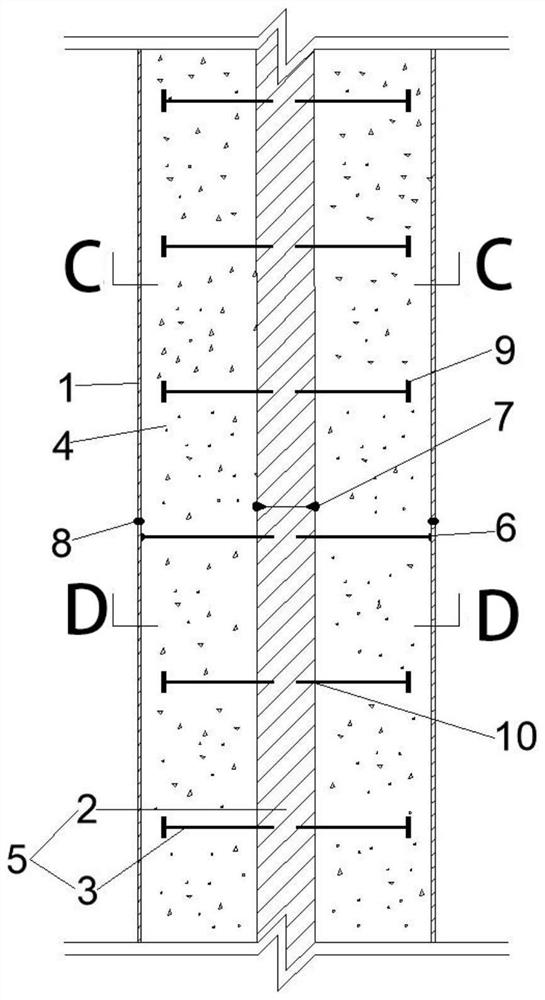
[0032] see image 3 and Figure 4 , the concrete-filled steel tubular column with the wolf-tooth core column provided by the present embodiment is basically the same as the embodiment 1, and its difference is that the steel bars on the wolf-tooth core are uniformly distributed by bolts 10 in the concrete-filled steel tube column of the above-mentioned wolf-tooth core column. Connected around the steel column, a steel end plate 9 is welded to the distal end of the ribbed steel bar that is not welded to the outer steel pipe. The reinforcement is screwed into the core column with threaded holes, which makes construction easier and the connection performance is not reduced.


PUM

PropertyMeasurementUnit
Angleaaaaaaaaaa

Abstract

The concrete-filled steel tube column comprises an outer steel tube, the wolf tooth core column located in the outer steel tube and concrete filled in the outer steel tube, the wolf tooth core column comprises a solid steel column and ribbed steel bars, the internally-arranged wolf tooth core column longitudinally penetrates through a column body, and the center of the wolf tooth core column coincides with the center of the outer steel tube; wherein the wolf tooth core column is connected with the ribbed steel bars. The solid steel columns and the ribbed steel bars connected with the solid steel columns are collectively called wolf tooth core columns. The ribbed steel bars are evenly distributed on the periphery of the built-in steel column in the mode of being perpendicular to the built-in steel column to form a wolf tooth-shaped core column. The core column is located in the center of the steel pipe and at least tightly connected with the eight ribbed steel bars with certain lengths, and the core column and the outer steel pipe form a whole after concrete is poured. The structural design is improved, the constraint performance of core concrete is improved, the bearing capacity of the column is improved, the plastic deformation of the column is reduced, the section size and material consumption of the concrete-filled steel tube column are reduced, and the column is economical and environmentally friendly.

Description

technical field [0001] The invention relates to the technical field of construction engineering, in particular to a concrete-filled steel tube column with a wolf-tooth core column. Background technique [0002] With the rapid development of my country's economy, the number of high-rise buildings is increasing day by day, so the requirements for the bearing capacity and seismic ductility of structural columns are also getting higher and higher. In order to meet the corresponding needs, the cross-sectional size of the structural load-bearing columns is also getting larger and larger, resulting in an increase in the self-weight of the structure and limited space for use. [0003] However, with the continuous emergence of super high-rise buildings, the cross-sectional dimensions of structural foundations and bottom / middle-story columns are still relatively large, resulting in a large amount of concrete and thick steel pipes, which is not conducive to the development of concrete ...

Claims


Application Information

Patent Timeline
IPC IPC(8): E04C3/36
CPCE04C3/36
Inventor 熊明祥皮鹏伟
Owner GUANGZHOU UNIVERSITY
Why Eureka
Try Eureka