Foldable tent

A technology for tents and tent frames, applied in tents/canopies, building types, buildings, etc., can solve the problems of insufficient strength of the canopy poles, and achieve the effect of fast and convenient opening and closing, and good strength

Pending Publication Date: 2022-07-29
WITH U E COMMERCE SHANGHAI CO LTD
View PDF0 Cites 0 Cited by
  • Summary
  • Abstract
  • Description
  • Claims
  • Application Information

AI Technical Summary

Problems solved by technology

However, existing tents may have the problem that the cornice poles are not strong enough after opening

Method used


Image

  • Foldable tent
  • Foldable tent
  • Foldable tent

Examples


Embodiment 1

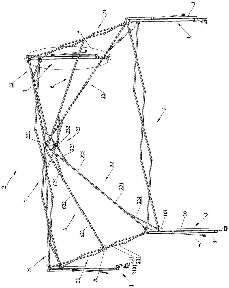
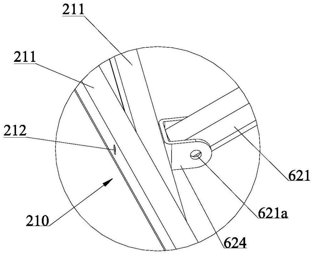
[0073] refer to Figure 1 to Figure 12 As shown, the foldable tent of this embodiment has an unfolded state and a folded state, and includes a foldable tent frame body 2; the tent frame body 2 can be independently supported on the ground, and the tent frame body 2 is covered with cloth A cover (not shown in the figure) is used for sunshade, wind and rain protection, etc.; a part of the cloth cover (for example, the edge part) can hang on the side of the tent frame main body 2, and this distribution cover is called a surrounding cloth. combine figure 1 and Figure 3 to Figure 5 As shown, the tent frame main body 2 includes a plurality of leg rods 1 extending in the up-down direction and a top frame connected to the upper part of the leg rods 1, which is supported on the ground by the leg rods 1, and the cloth cover mainly covers the top frame. The tent also includes an overhanging rod 3 having an inner end and an outer end, and the inner end of the overhanging rod 3 is rotata...

Embodiment 2

[0087] This embodiment is basically the same as Embodiment 1, and the only difference is that the strengthening mechanism 6 is different. refer to Figures 14 to 16 As shown, the reinforcing mechanism 6 of this embodiment is connected between the eaves frame 21 and the top rod unit 22 . The reinforcement mechanism 6 includes a reinforcement rod 610, one end of the reinforcement rod 610 is rotatably connected to the inner top rod 222, and the other end is rotatably connected to the eaves frame 21 (specifically, the upper part of the two adjacent link assemblies 210 is at the top). of the rotating connection). Specifically, one end of the reinforcing rod 610 is pivotally connected to the inner top rod 222, and the distance between the connection between the two and the inner end of the inner top rod 222 is less than one third of the length of the inner top rod 222; the reinforcing rod 610 The other end of the connecting rod is pivotally connected to a connecting head 611 , and...

Embodiment 3

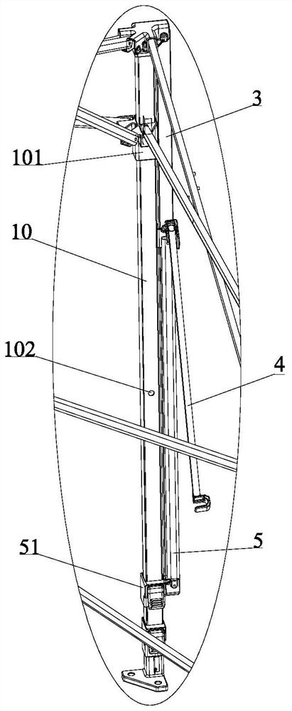
[0090] This embodiment is basically the same as Embodiment 1, and the difference is only that: the connection mode of the overhang rod 3 and the main body of the tent frame is different; Figure 17 to Figure 19 As shown, the overhang rod 3 is detachably inserted into the leg rod 1 instead of being rotatably connected with the leg rod 1 . Specifically, the inner end of the overhang rod 3 is detachably plugged into the leg rod 1 through the sliding sleeve 101 on the leg rod 1 . The sliding sleeve 101 is provided with a slot 101a, and the slot 101a generally extends obliquely. When the overhang rod 3 is in the open state, the inner end of the overhang rod 3 is inserted into the slot 101a and connected with the leg rod 1; when the overhang rod 3 is in the folded state, the inner end of the overhang rod 3 is inserted from the slot 101a. Pull out from the middle and disengage from the leg bar 1. Although the cross bar is not shown, the cross bar can also be automatically disengage...


PUM


Abstract

The invention provides a foldable tent which comprises a tent frame main body, cornice rods and surrounding cloth. The eave frame is connected between the two adjacent leg rods; after the foldable tent is unfolded, the cornice rods have an unfolded state and a folded state; when the cornice rods are in the open state, the inner ends of the cornice rods are connected to the tent frame body, the outer ends of the cornice rods deviate from the leg rods by a certain distance, and the cornice rods are transverse to the leg rods so that the surrounding cloth can be supported; when the cornice rods are in a folded state, the surrounding cloth is perpendicular to the side of the tent frame body. The foldable tent further comprises a cross rod, and the two ends of the cross rod are used for being connected with the eave frame and the cornice rod respectively, so that the strength of the cornice rod of the foldable tent is enhanced when the cornice rod is in an open state. According to the tent, the cornice rods can be flexibly selected to be unfolded or folded according to needs, and meanwhile the strength of the cornice rods is good after the cornice rods are unfolded.

Description

technical field [0001] The invention belongs to the field of outdoor articles, and relates to a collapsible tent, in particular to a collapsible tent with eaves poles. Background technique [0002] Tent is widely used in outdoor activities, such as outdoor camping, etc. It can not only prevent wind, rain, mosquitoes, but also keep warm. The traditional foldable tent has a small shading area. In order to increase the shading area after the tent is opened, the overhanging tent with an overhanging structure has appeared. The edge on the overhang rod achieves the purpose of increasing such an area. This kind of tent mainly connects the overhang rod or inserts the overhang rod on the top rod of the canopy bracket. After the tent body is unfolded, the overhang wire rod can be selectively extended to increase the shading area. However, the existing tents may have the problem that the strength of the overhang poles is insufficient after being opened. SUMMARY OF THE INVENTION ...

Claims


Application Information

Patent Timeline
IPC IPC(8): E04H15/50E04H15/32
CPCE04H15/50E04H15/505E04H15/32
Inventor 袁春亮杨胜勇
Owner WITH U E COMMERCE SHANGHAI CO LTD
Why Eureka
Try Eureka