Backlight module and method for reducing thickness of backlight module

A backlight module and light source technology, which is applied to the semiconductor devices of light-emitting elements, light sources, optics, etc., can solve the problems of dark areas in the backlight module, increase in the thickness of the backlight module, etc., and achieve the goal of reducing the thickness and expanding the illuminated area Effect

Pending Publication Date: 2022-07-29
FOUR SUN TECH (WUJIANG) CO LTD
View PDF0 Cites 0 Cited by
  • Summary
  • Abstract
  • Description
  • Claims
  • Application Information

AI Technical Summary

Problems solved by technology

Since there is a gap in the irradiation range of the lamp beads on the light board on the optical board, dark areas will appear in the backlight module during use. In order to eliminate the dark areas, the distance be

Method used


Image

  • Backlight module and method for reducing thickness of backlight module
  • Backlight module and method for reducing thickness of backlight module
  • Backlight module and method for reducing thickness of backlight module

Examples


Embodiment 2

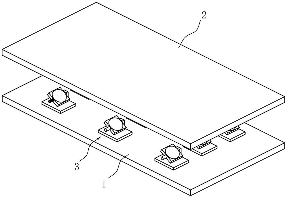
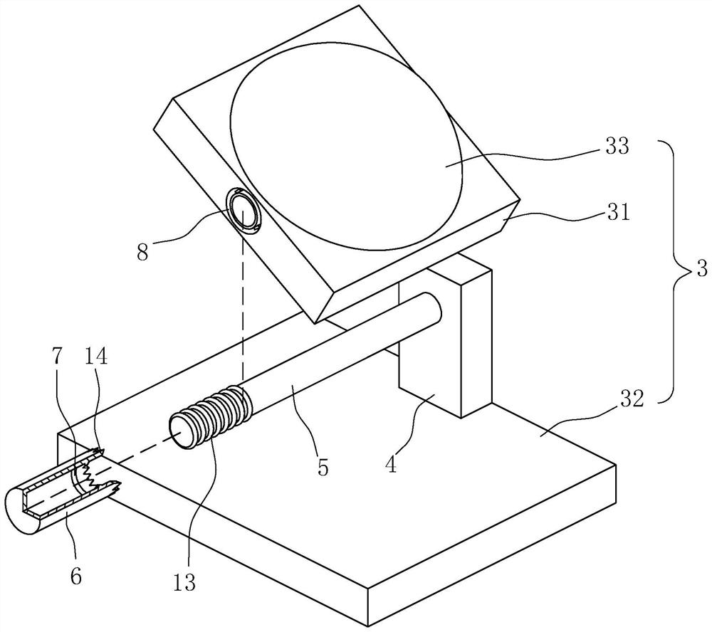
[0043] refer to figure 2 and image 3 , the difference between Embodiment 2 and Embodiment 1 is that: the lamp bead 3 includes a base 32, a light source 31 and a lens 33, the base 32 is arranged on the mounting plate 1, and one end of the top surface of the base 32 is fixed with a fixing block 4. A connecting shaft 5 is fixed on the side wall, the housing of the light source 31 is arranged on the connecting shaft 5 , the light source 31 can rotate around the connecting shaft 5 , and the lens 33 is fixed on the housing of the light source 31 . The end of the connecting shaft 5 away from the fixing block 4 is provided with a limiting member for limiting the rotation of the lamp beads 3 . The light source 31 rotates on the connecting shaft 5, which is convenient to adjust the direction of the light, and it is convenient to adjust the direction of the light according to different design requirements.

[0044] refer to figure 2 and image 3 In this embodiment, the limiting me...


PUM


Abstract

The invention relates to a backlight module and a method for reducing the thickness of the backlight module, the backlight module comprises a lamp panel and an optical plate, the optical plate is arranged above the lamp panel, the lamp panel comprises a mounting plate and a plurality of lamp beads, the plurality of lamp beads are arranged on the mounting plate at intervals, and the illumination directions of the plurality of lamp beads are all inclined. The method further comprises the following steps that firstly, lamp beads are prepared, and after the lamp beads are installed, light is emitted upwards in an inclined mode; and secondly, the lamp beads are fixed to the mounting plate, the directions of the lamp beads are the same, and an optical plate is arranged above the mounting plate. The backlight module has the advantages that normal illumination of the lamp beads is kept, and the thickness of the backlight module is reduced.

Description

technical field [0001] The present application relates to the field of optical devices, and in particular, to a backlight module and a method for reducing the thickness of the backlight module. Background technique [0002] The backlight module is composed of a light board and a plurality of optical boards arranged above the light board. The gap between the light board and the optical board above it is the light mixing space. Since there is a gap between the light beads on the light board and the illumination range of the optical board, a dark area will appear when the backlight module is in use. In order to eliminate the dark area, the distance between the optical board and the light board will be increased, and the lamp beads will be enlarged The irradiated area on the optical plate, but this also leads to an increase in the thickness of the backlight module. SUMMARY OF THE INVENTION [0003] In order to reduce the thickness of the backlight module, the present applica...

Claims


Application Information

Patent Timeline
IPC IPC(8): F21V19/00F21Y115/10G02F1/13357
CPCF21V19/0015F21Y2115/10G02F1/133603G02F1/133608
Inventor 王钰鑫林炳腾
Owner FOUR SUN TECH (WUJIANG) CO LTD
Why Eureka
Try Eureka