Leakage circuit breaking device of electrical equipment

A leakage circuit breaker and electrical equipment technology, which is applied in the field of leakage circuit breakers, can solve problems such as easy loss of working ability, and achieve the effects of improving installation convenience, ensuring stability, and improving heat dissipation

Active Publication Date: 2022-07-29
南通盛天电气科技有限公司
View PDF5 Cites 0 Cited by
  • Summary
  • Abstract
  • Description
  • Claims
  • Application Information

AI Technical Summary

Problems solved by technology

[0003] In order to solve the above technical problems, the present invention provides a leakage circuit breaker for electrical equipment, which solves the problem that the traditional small leakage circuit breaker easily loses its working ability after its own heat reaches a certain limit

Method used


Image

  • Leakage circuit breaking device of electrical equipment
  • Leakage circuit breaking device of electrical equipment
  • Leakage circuit breaking device of electrical equipment

Examples


Embodiment 1

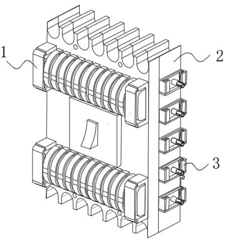
[0030] like Figure 1-Figure 8 As shown in the figure, a leakage circuit breaker for electrical equipment according to the present invention includes a circuit breaker main body 2, and a constant temperature device 1 is symmetrically arranged on the front of the circuit breaker main body 2. By setting the constant temperature device 1, the leakage current of the electrical equipment can be improved. The working performance of the circuit breaker, and the front surface of the circuit breaker main body 2 is fixedly connected to the back of the thermostat device 1, and the two ends of the circuit breaker main body 2 are evenly provided with plug-in devices 3. By arranging the plug-in devices 3, this kind of electrical equipment can be improved. The heat dissipation effect of the leakage circuit breaker is improved, and the inner wall of the plug-in device 3 is fixedly connected with both ends of the circuit breaker main body 2;

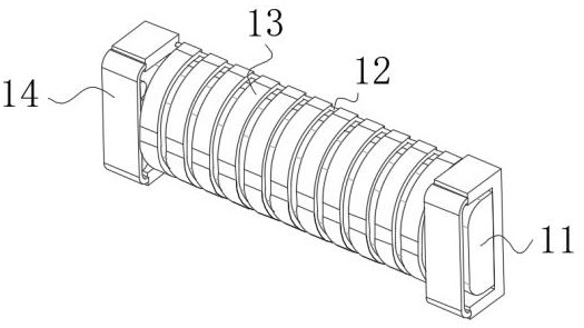
[0031] The thermostatic device 1 includes a fasten...

Embodiment 2

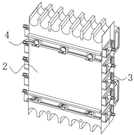
[0038] like Figure 1-Figure 8 As shown in the present invention, a leakage circuit breaker for electrical equipment according to the present invention, on the basis of the first embodiment, the plug device 3 includes a receiving frame 36. The circuit breaker is movably connected, so that there is no tight connection between the leakage circuit breakers of this kind of electrical equipment, which is conducive to its heat dissipation. The interior of the storage frame 36 is provided with a movable plate 33, and the inner wall of the storage frame 36 is connected to the movable plate. The bottom of 33 is in contact with each other, and the plug-in cylinder 31 and the limit cylinder 35 provided outside the plug-in device 3 are used in conjunction, so that the leakage circuit breaker of the electrical equipment can be movably connected, which improves the installation of the leakage circuit breaker of the electrical equipment. For convenience, two ends of the movable plate 33 are ...


PUM


Abstract

The invention discloses an electric leakage circuit breaker of electrical equipment, which comprises a circuit breaker main body, constant temperature devices are symmetrically arranged on the front surface of the circuit breaker main body, the front surface of the circuit breaker main body is fixedly connected with the back surfaces of the constant temperature devices, and plugging devices are uniformly arranged at two ends of the circuit breaker main body. The inner wall of the plugging device is fixedly connected with the two ends of the circuit breaker main body, the constant temperature device comprises a fastening device, a heat dissipation copper plate is arranged in the fastening device, the inner wall of the fastening device is movably connected with the two ends of the heat dissipation copper plate, and contact devices are uniformly arranged on the outer surface of the heat dissipation copper plate. The outer surface of the heat dissipation copper plate is movably connected with the inner wall of the contact device, and the two ends of the contact device are symmetrically provided with fixing rods. The problem that a traditional small electric leakage circuit breaker easily loses the working capacity after the heat of the device reaches a certain limit is solved.

Description

technical field [0001] The invention relates to the field of electrical equipment, in particular to a leakage circuit breaker for electrical equipment. Background technique [0002] The small leakage circuit breaker is a current-limiting circuit breaker with overload and short-circuit protection. At present, the small leakage circuit breaker on the market includes a small leakage circuit breaker body. Although this leakage circuit breaker body can prevent personal electric shock , but because the usual small leakage circuit breaker body works in a high-temperature working environment, and when the heat generated by itself reaches a certain limit, the small leakage circuit breaker will lose its working ability, so the heat dissipation effect of the small leakage circuit breaker is improved. It is a current problem to improve the heat dissipation effect while ensuring the structural strength. A leakage circuit breaker for electrical equipment is proposed to solve the above-men...

Claims


Application Information

Patent Timeline
Patent Type & Authority Applications(China)
IPC IPC(8): H01H9/52H01H71/02
CPCH01H9/52H01H71/0207
Inventor 蒋欣蒋耀
Owner 南通盛天电气科技有限公司
Why Eureka
Try Eureka