Electric connector and connector assembly

An electrical connector and electrical connection technology, applied in the direction of connection, connecting device parts, contact parts, etc., can solve problems such as unfavorable large current transmission, long transmission path, and electrical connectors that do not meet the requirements, and achieve the benefits of large currents. The effect of the transmission of electric current

Active Publication Date: 2022-07-29
DEYI PRECISION ELECTRONIC IND CO LTD PANYU
View PDF11 Cites 0 Cited by
  • Summary
  • Abstract
  • Description
  • Claims
  • Application Information

AI Technical Summary

Problems solved by technology

When the second element is inserted into the slot, the second element abuts against the contact portion, and the free end abuts against the first conductor, so that the second element is electrically conductive through the second conductor. connected to the first conductor, therefore, the current on the second element first passes through the contact portion, then passes through the first segment or / and the second segment to the first conductor, and finally passes through the The first conductor with higher conductivity is transmitted to the first element, wherein the current will pass through the first section or / and the second section with poor conductivity and longer length, resulting in a longer transmission path. Long, not conducive to the transmission of large current
And when the second element is relatively large and thick, the electrical connector of this type does not meet the requirements very much

Method used


Image

  • Electric connector and connector assembly
  • Electric connector and connector assembly
  • Electric connector and connector assembly

Examples


Embodiment Construction

[0053] In order to facilitate a better understanding of the purpose, structure, features and effects of the present invention, the present invention will now be further described with reference to the accompanying drawings and specific embodiments.

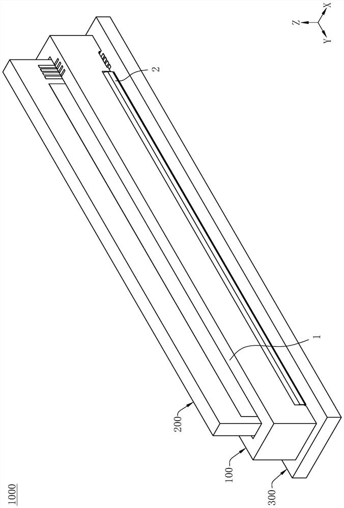
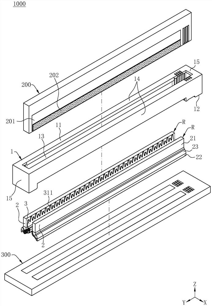
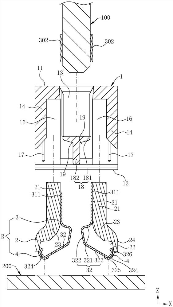
[0054] like figure 1 As shown, it is the connector assembly 1000 of the present invention, the connector assembly 1000 includes a first element 200 , a second element 300 , and is electrically connected to one of the first element 200 and the second element 300 An electrical connector 100 between the two is defined. In order to facilitate the description of the connector assembly 1000 and the specific structure of the electrical connector 100, a front-rear direction X, a left-right direction Y, and an up-down direction Z are defined.

[0055] like figure 2 and Figure 5 As shown, the first component 200 is provided with solder 202 on the solder pads 201 on the front and rear sides of the first component 200 . The electrical co...


PUM


Abstract

The invention discloses an electric connector, comprising: an insulating housing having a slot concavely arranged downwards from a butt joint surface of the insulating housing, for a first element to be inserted therein; the at least one conductive component is fixedly held on the insulating shell and is positioned on at least one side of the slot, the conductive component comprises a first conductor with high conductivity and a second conductor with good elasticity, a conductive connection part of the first conductor is used for conductively connecting the first element, the second conductor is provided with a fixed part and an elastic arm formed by extending downwards from the fixed part, and the elastic arm is provided with a contact part and an abutting part; the contact part is located between the fixing part and the abutting part, the contact part is used for elastically abutting against the second element downwards, the abutting part is used for elastically abutting against the first conductor in the front-back direction, and the second conductor has a first length extending between the fixing part and the contact part and a second length extending between the contact part and the abutting part; the first length is greater than the second length. A connector assembly including a first element, a second element, and an electrical connector connecting the two is disclosed. The second length is shortened, and transmission of large current is facilitated.

Description

【Technical field】 [0001] The present invention relates to an electrical connector and a connector assembly, in particular to an electrical connector suitable for transmitting large current and a connector assembly having the electrical connector. 【Background technique】 [0002] A known electrical connector is used to transmit large current, which electrically connects a first element and a second element, and includes an insulating body and two conductive components fixed on the insulating body, each of which is The conductive component has a first conductor and a second conductor, the insulating body has a slot for inserting the first element, and the conductivity of the first conductor is greater than that of the second conductor The elasticity of the second conductor is better than the elasticity of the first conductor. The first conductor has a lead portion extending out of the insulating body, and the two lead portions of the two conductive components are connected to e...

Claims


Application Information

Patent Timeline
Patent Type & Authority Applications(China)
IPC IPC(8): H01R13/22H01R13/02H01R13/42H01R13/629
CPCH01R13/22H01R13/02H01R13/42H01R13/629
Inventor 周志勇
Owner DEYI PRECISION ELECTRONIC IND CO LTD PANYU
Why Eureka
Try Eureka