
Synchronous playing method and system and LED display screen

A technology for synchronous playback and playback time, applied in image communication, selective content distribution, electrical components, etc., can solve problems such as internal clock not being highly accurate, tearing, media out of sync, etc., to improve playback quality and efficiency, reduce screen tearing effect

Pending Publication Date: 2022-07-29
SHENZHEN AOTO ELECTRONICS
View PDF4 Cites 0 Cited by
  • Summary
  • Abstract
  • Description
  • Claims
  • Application Information

AI Technical Summary

Problems solved by technology

[0003] As with any device, its internal clock is not highly accurate nor consistent across devices, one mechanism may vibrate faster or slower than another, when played together this can cause the media to be out of sync, even with The host time stamp synchronization method, but because the computer time stamp is not associated with the information of each video frame, no matter how to control its synchronization, there will still be a torn picture in the end
In fact, when multiple devices are seamlessly spliced ​​together, such as the application of LED seamless splicing, the picture cannot achieve true frame synchronization, especially for MicroLED displays with smaller lamp chips and high-definition displays and multiple In the case of splicing sources, the tearing phenomenon of the picture is more obvious

Method used


Image

  • Synchronous playing method and system and LED display screen
  • Synchronous playing method and system and LED display screen
  • Synchronous playing method and system and LED display screen

Examples


Embodiment Construction

[0044] In order to more clearly understand the above objects, features and advantages of the present application, the present application will be described in detail below with reference to the accompanying drawings and specific embodiments. It should be noted that the embodiments of the present application and the features of the embodiments may be combined with each other unless there is conflict. Unless otherwise defined, all technical and scientific terms used herein have the same meaning as commonly understood by one of ordinary skill in the technical field to which this application belongs. The terms used herein in the specification of the present application are only for the purpose of describing specific embodiments, and are not intended to limit the present application.

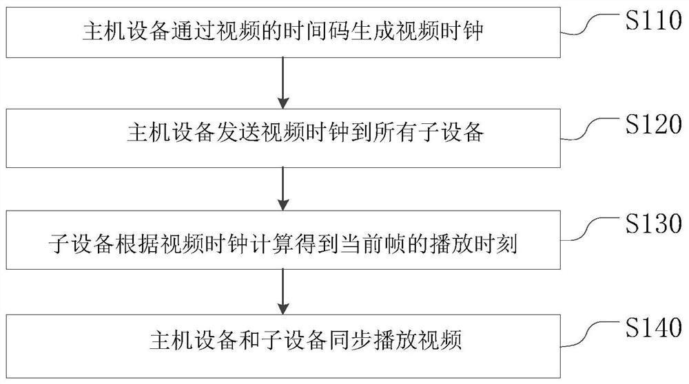
[0045] see figure 1 , figure 1 A flowchart of a synchronous playback method according to an embodiment of the present invention; the synchronous playback method includes:

[0046] Step S110, the h...


PUM


Abstract

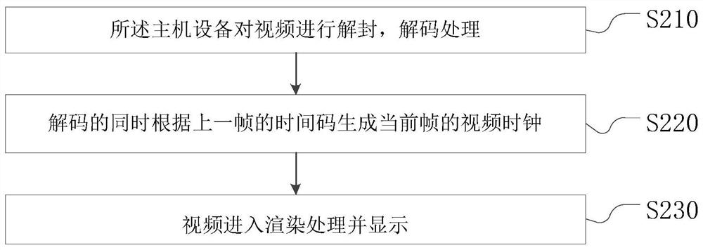
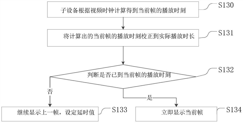
The invention relates to a synchronous playing method and system and an LED display screen. The synchronous playing method comprises the steps that host equipment generates a video clock through a time code of a video; sending a video clock to all sub-devices; the sub-device calculates the playing moment of the current frame according to the video clock; and the host equipment and the sub-equipment synchronously play the video. Wherein the specific steps of synchronously playing the video by the host equipment and the sub-equipment are as follows: correcting the calculated playing moment of the current frame to the actual playing duration; judging whether the playing moment of the current frame is reached or not; if not, continuing to display the previous frame, and setting a delay value; and if yes, immediately displaying the current frame. According to the method, an external time code generator is not needed during multi-device media playing, the host device generates the video clock through the time code in the video decoding process, the host device and the sub-devices are synchronized, the working process is reasonably configured, and the phenomenon of picture tearing is avoided while the efficiency is improved.

Description

technical field [0001] The application of the present invention belongs to the technical field of synchronous playback, and in particular relates to a synchronous playback method, a system and an LED display screen. Background technique [0002] When multiple devices play the same program source or multiple splicing sources synchronously, the method commonly used on the market is to use the timestamp method, that is, the synchronization host notifies the media playback process on multiple playback devices within a certain period of time to perform synchronous playback. This method can deceive human eyes, because the display terminals are usually scattered and not spliced ​​together, so that the human eyes appear to be synchronized by this method. [0003] Any device whose internal clock is not highly accurate or consistent across devices, one mechanism may vibrate faster or slower than another, which can cause media to be out of sync when played together, even with The host...

Claims


Application Information

Patent Timeline
IPC IPC(8): H04N21/43H04N21/44H04N21/41
CPCH04N21/4307H04N21/44H04N21/4122
Inventor 吴未梁德斌吴振志吴涵渠
Owner SHENZHEN AOTO ELECTRONICS
Learn More