
Seamless switching between random access units multiplexed in a multi angle view multimedia stream

a multi-angle view and multi-angle view technology, applied in the field of multi-angle view multi-angle view multimedia stream, can solve the problem of invariability of frame ra

Active Publication Date: 2007-07-26
PANASONIC CORP
View PDF9 Cites 17 Cited by
  • Summary
  • Abstract
  • Description
  • Claims
  • Application Information

AI Technical Summary

Benefits of technology

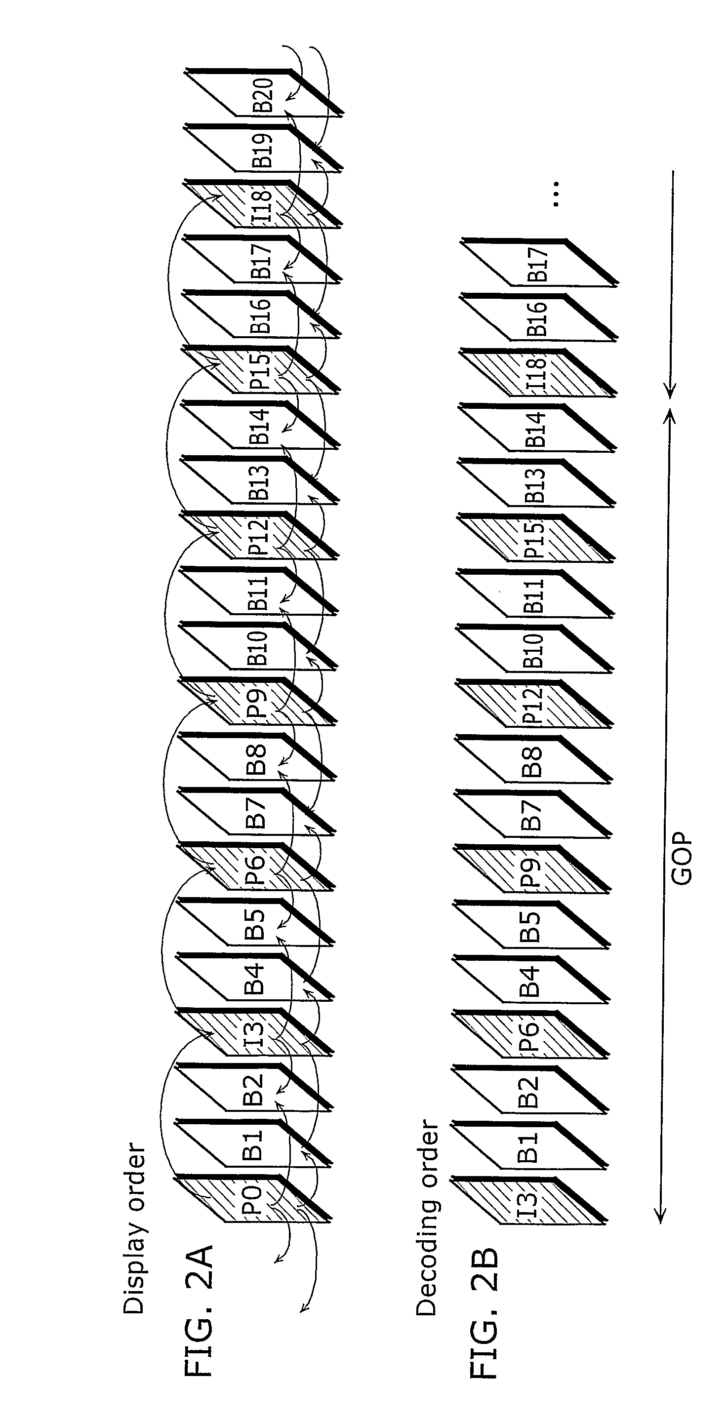
[0043] In this way, coded streams are generated so that delay amounts (frame delays) of two access units (such as clips) on which special playback is performed become equal to each other. Therefore, no gap occurs at the connection of these access units at the time when these access units are decoded in sequence. In other words, these access units are connected to each other seamlessly at the time of special playback. This means the frame rates become invariable. Consequently, it becomes possible to eliminate making a user who watches a moving picture made up of these access units feel uncomfortable. Here, for example, coded streams are generated so that the delay amounts of these two access units are adjusted to predetermined delay amounts in the case where delay amounts are predetermined according to the operation standard of an application program.
[0045] In this way, the demultiplexing apparatus can easily obtain the delay amounts in these two access units through the delay information in the case where the delay information (frame delay information) indicates delay amounts. Also, the demultiplexing apparatus can easily obtain the delay amounts in these two access units in the case where a flag as delay information indicates that the delay amounts of these two access units are equal to each other. Consequently, it is possible to cause the demultiplexing apparatus to perform more proper demultiplexing processing.
[0046] Also, in the second aspect of the present invention, the coding unit may generate the coded streams so that no gap occurs at a connection of the two access units in all of the access units included in the coded streams, the connection being an angle changeable point.
[0047] Since these two access units have a different angle, no gap occurs at the connection of these access units at the time when these access units are decoded in sequence likewise the earlier described case. In other words, these access units are connected in a seamless multi-angle manner. This means that the frame rates are invariable. Consequently, it becomes possible to eliminate making a user who watches a moving picture made up of these access units with a different angle feel uncomfortable.
[0049] In an example case where coded streams are generated so that delay amounts of these two access units (such as clips) on which special playback is performed, it becomes possible to decode and play back these two access units in sequence without allowing the occurrence of a gap at the connection of these two access units at the time of special playback. In other words, it becomes possible to connect these access units seamlessly. This means that it becomes possible to make the frame rates invariable. Consequently, it also becomes possible to eliminate making a user who watches the moving picture made up of these access units feel uncomfortable. Also, in an example case where delay amounts are indicated by delay information (frame delay information), it is possible to easily obtain the delay amounts of these two access units through the delay information. Further, in the case where the delay information is indicated using a flag, it is possible to easily obtain the information indicating that the delay amounts of these two access units are equal to each other. Consequently, it is possible to perform more proper demultiplexing processing.
[0058] Up to this point, since the present invention makes it possible to guarantee display with a fixed frame rate even at the time of special playback, it is possible to eliminate making a user feel uncomfortable. Especially, the present invention makes it possible to improve the playback quality of a package medium, and thus it is highly practical. FURTHER INFORMATION ABOUT TECHNICAL BACKGROUND TO THIS APPLICATION

Problems solved by technology

This means the frame rates become invariable.

Method used


Image

  • Seamless switching between random access units multiplexed in a multi angle view multimedia stream
  • Seamless switching between random access units multiplexed in a multi angle view multimedia stream
  • Seamless switching between random access units multiplexed in a multi angle view multimedia stream

Examples


first embodiment

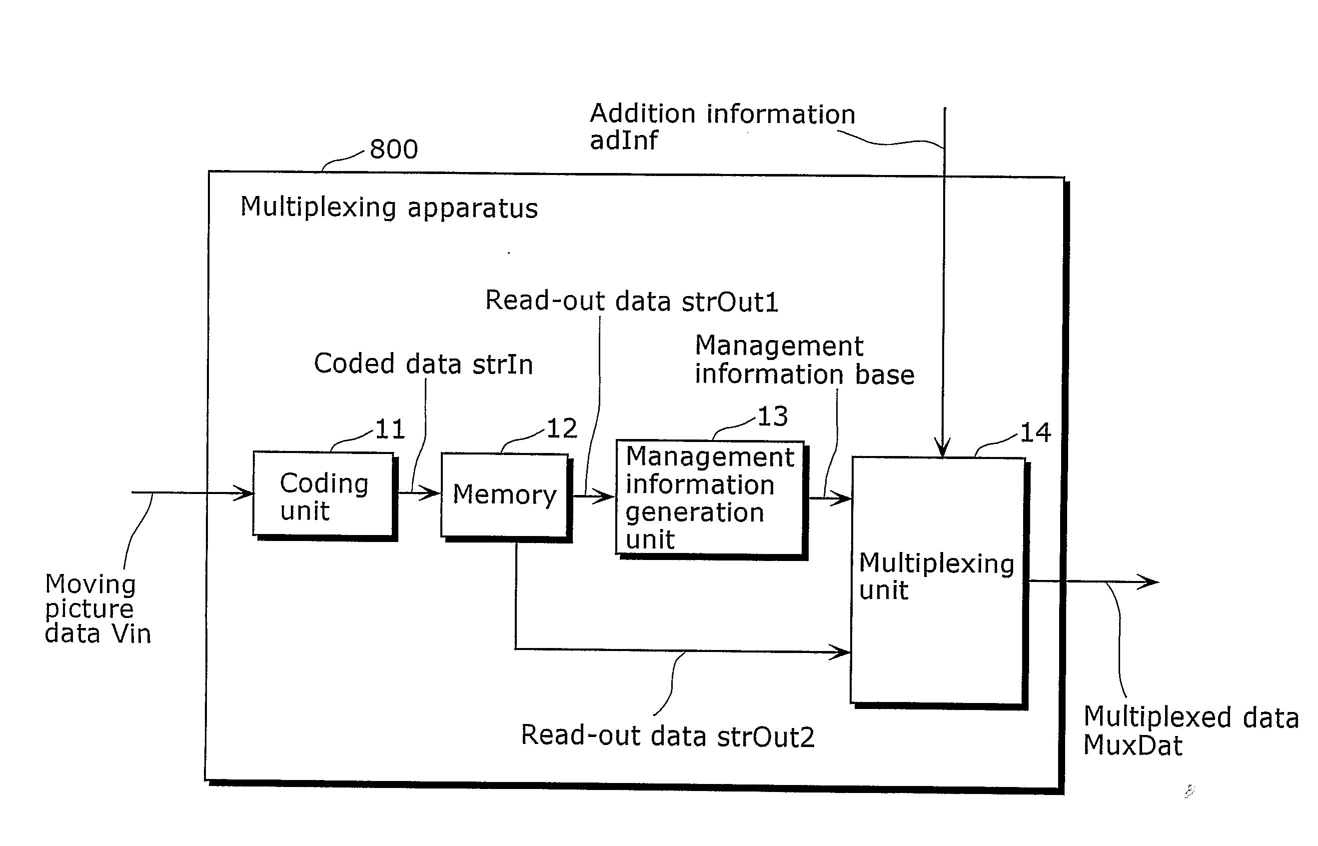
[0093]FIG. 13 is a flow chart showing the operation of the multiplexing apparatus in a first embodiment of the present invention. The multiplexing apparatus outputs multiplexed data that can indicate frame delay information of the coded stream to be stored in the multiplexed data.

[0094] First, in Step 301, the multiplex apparatus generates MPEG-4 AVC coded streams. In Step 302, it obtains frame delays of the coded stream generated in Step 301, and goes to Step 303. In Step 303, it judges whether or not all the coded streams to be stored in the multiplexed data have already been generated, and repeats processing of Step 301 and Step 302 until all the coded streams have been generated. In Step 304, it generates frame delay information to be stored as management information of multiplexed data, and goes to Step 305. In Step 305, it generates management information indicating frame delay information in addition to the information generated by a conventional multiplexing apparatus. Last...

second embodiment

[0111]FIG. 16 is a flow chart showing the operation of the multiplexing apparatus in a second embodiment of the present invention.

[0112] First, in Step 401, the multiplexing apparatus sets the value of frame delay used in common in the coded stream to be stored in the multiplexed data. In Step 402, it generates MPEG-4 AVC coded streams based on the frame delay that has been set in Step 401. In Step 403, it judges whether all the coded streams to be stored in the multiplexed data have already been generated, and repeats the processing of Step 402 until all the coded streams are coded. In Step 404, it generates frame delay information to be stored as management information of the multiplexed data, and then goes to Step 405. In Step 405, it generates management information indicating frame delay information in addition to the information generated by the conventional multiplexing apparatus. Lastly, in Step 406, it multiplexes the coded streams generated in Step 401 and the management ...

third embodiment

[0127]FIG. 18 is a flow chart indicating the operation of the demultiplexing apparatus in a third embodiment of the present invention. The demultiplexing apparatus inputs and plays back the multiplexed data generated by the demultiplexing apparatus in the first and second embodiments.

[0128] First, in Step 501, the demultiplexing apparatus demultiplexes the multiplexed data to obtain the management information, and obtains the information concerning the clips to be played back. Clips to be played back are determined based on the playback order predetermined by an instruction from a user or in a play list in the management information or the like.

[0129] Next, in Step 502, it obtains frame delay information of the clips determined as the clips to be played back in Step 501, and goes to Step 503. In Step 503, it determines the frame delay at the time of playing back the clips based on the frame delay information obtained in Step 502.

[0130] In Step 504 and Step 505, it decodes and dis...


PUM


Abstract

The multiplexing apparatus which does not make a user who watches a moving picture feel uncomfortable, the moving picture including: (i) a coding unit (42) for generating one or more coded streams so that no gap occurs at the connection of predetermined two access units in a process of decoding, in sequence, the two access units in all of the access units included in the coded streams; and (ii) a multiplexing unit (18) for multiplexing, with other information, the coded streams generated in the coding unit (42).

Description

TECHNICAL FIELD [0001] The present invention relates to a multiplexing apparatus for multiplexing one or more coded streams including coded pictures with other information so as to generate multiplexed data and a demultiplexing apparatus for demultiplexing the multiplexed data. The present invention especially relates to a multiplexing apparatus and a demultiplexing apparatus which can perform special playback such as multi-angle playback or the like. BACKGROUND ART [0002] Recently, the multi-media era has come in which sound, pictures and other pixel values are integrated into one media, and conventional information media as communication tools like newspapers, magazines, TV, radio and telephone are regarded as the targets of multi-media. Generally, multi-media is a form of simultaneous representation of not only characters but also graphics, sound, and especially pictures. In order to handle the above-described conventional information media as multi-media, it is a requisite to re...

Claims


Application Information

Patent Timeline
Patent Type & Authority Applications(United States)
IPC IPC(8): H04N11/04H04N5/92H04N7/173H04N7/58H04N19/00H04N19/42H04N19/46H04N19/51H04N19/70H04N21/2187H04N21/236H04N21/2365H04N21/242H04N21/426H04N21/434H04N21/44
CPCH04N21/23614H04N21/4348G11B27/105H04N21/42646G11B27/322G11B2220/2541G11B27/3027H04N21/2365
Inventor TOMA, TADAMASAOKADA, TOMOYUKIKADONO, SHINYA
Owner PANASONIC CORP
Learn More