Fixture for machining submersible pump shell blank

A blank processing, submersible pump technology, applied in the direction of grinding workpiece supports, etc., can solve the problems of easy jumping, low processing accuracy of submersible pump body blanks, and difficulty in ensuring reliable contact between clamping jaws and submersible pump pump body blanks, etc. Not easy to jump effect

Active Publication Date: 2022-08-02
慈溪汇丽机电股份有限公司
View PDF6 Cites 0 Cited by
  • Summary
  • Abstract
  • Description
  • Claims
  • Application Information

AI Technical Summary

Problems solved by technology

Chuck clamping is usually used for the processing of this cylindrical shell, because the outer peripheral surface of the submersible pump body blank is uneven, so it is difficult to ensure that all the jaws are in reliable contact with the submersible pump body blank when clamping it. , so that the submersible pump body blank is prone to beating during turning, resulting in low machining accuracy of the submersible pump body blank

Method used


Image

  • Fixture for machining submersible pump shell blank
  • Fixture for machining submersible pump shell blank
  • Fixture for machining submersible pump shell blank

Examples


Embodiment 1

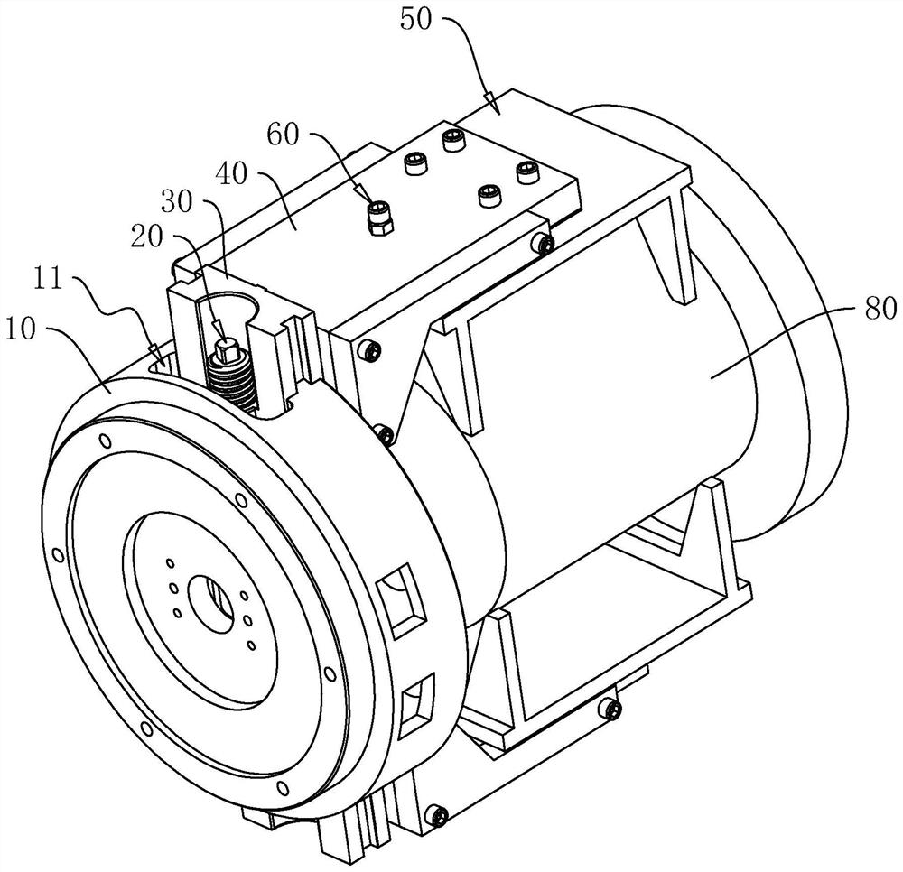
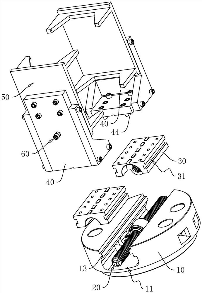
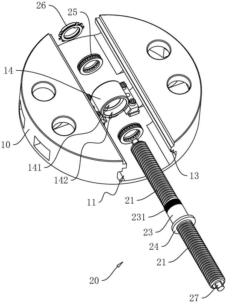
[0044] refer to figure 1, The submersible pump housing blank processing fixture includes a chuck body 10 , a two-way screw 20 , a slider 30 , a support plate 40 and a clamping jaw 50 . The two-way screw 20 is rotatably connected to the chuck body 10 , the two-way screw 20 is fixed relative to the chuck body 10 along its own axial direction, and the slider 30 is slidingly connected to the chuck disc along the radial direction of the chuck body 10 . On the body 10, the two-way screw 20 has two transmission threaded portions 21 with opposite directions of rotation. The two sliding blocks 30 are connected with threads, the supporting plates 40 are fixed on the sliding blocks 30 in a one-to-one correspondence, and the clamping jaws 50 are fixed on the supporting plates 40 in a one-to-one correspondence. Rotating the two-way screw 20 can drive the two clamping jaws 50 to be close to each other to clamp the blank 80 .

[0045] refer to figure 2 and image 3 , the chuck body 10 i...

Embodiment 2

[0058] refer to Figure 5 The difference between this embodiment and the first embodiment is that the support plate 40 provides support for the clamping jaw 50 through the swing column 512 and the swing groove 43 . Specifically, a swing column 512 is fixed on the side of the base plate 51 close to the support plate 40 . The axis of the swing column 512 and the axis of the chuck body 10 are perpendicular to each other. The side of the support plate 40 close to the base plate 51 is provided with a swing slot 43 , two ends of the swing slot 43 penetrate two opposite side walls of the support plate 40 , and the swing column 512 can slide from one end of the swing slot 43 and be inserted into the swing slot 43 to swing. The post 512 rotates relative to the support plate 40 about its own circumference. When the swing column 512 is inserted into the swing slot 43 , there is a deformation gap between the base plate 51 and the support plate 40 .

[0059] The difference between this e...


PUM


Abstract

The invention relates to a clamp for machining a submersible pump shell blank, and relates to the field of clamps. The clamp comprises a chuck body provided with a sliding groove formed in the radial direction of the chuck body; the two-way lead screw is rotationally connected into the sliding groove, the two-way lead screw is fixed relative to the chuck body in the axial direction of the two-way lead screw, and the two-way lead screw is provided with two transmission thread parts with opposite rotating directions; the sliding blocks are connected into the sliding grooves in a sliding mode in the axial direction of the two-way lead screw, and the two sliding blocks are in threaded connection with the two transmission threaded parts of the two-way lead screw correspondingly; the supporting plate is arranged on the sliding block and slides in the axial direction of the bidirectional lead screw along with the sliding block. The clamping jaws are arranged on the supporting plate, the two clamping jaws are oppositely arranged, the supporting plate provides a supporting area for the clamping jaws, the supporting area is located in the middle of the clamping jaws, each clamping jaw is provided with two sets of clamping points arranged at intervals in the axial direction of the chuck body, the supporting area is located between the two sets of clamping points, and each set of clamping points comprises two clamping points; and each group of clamping points can swing relative to the supporting area. The blank clamping device has the effect of reliably clamping the blank.

Description

technical field [0001] The present application relates to the field of fixtures, and in particular, to a fixture for machining a blank of a submersible pump housing. Background technique [0002] A chuck is a mechanical device used on a machine tool to clamp a workpiece. A machine tool accessory that clamps and positions the workpiece by the radial movement of the movable jaws evenly distributed on the chuck body. The chuck is generally composed of three parts: the chuck body, the movable jaw and the jaw drive mechanism. [0003] In related technologies, there are often some revolving body blanks, such as submersible pump body blanks, which are arranged in a cylindrical shape. In the production of submersible pump bodies, the submersible pump body blanks are first produced by casting. , and then grind the submersible pump body blank to remove its redundant parts. Chuck clamping is usually used when machining such a cylindrical shell. Because the outer peripheral surface o...

Claims


Application Information

Patent Timeline
Patent Type & Authority Applications(China)
IPC IPC(8): B24B41/06
CPCB24B41/06
Inventor 吴广铭伍燚科黄强卢听听罗骏峰
Owner 慈溪汇丽机电股份有限公司
Why Eureka
Try Eureka