Die opening method of core shooter

A core shooter and core mold technology, applied in molding machines, casting molding equipment, metal processing equipment, etc., can solve the problems affecting the socket end accuracy of ductile iron pipes, low sand core accuracy, sand core damage, etc., to achieve Reduce the probability of damage, improve accuracy and yield, and improve the effect of accuracy

Inactive Publication Date: 2020-11-13
济南柳玉鑫机械设备有限公司
View PDF7 Cites 0 Cited by
  • Summary
  • Abstract
  • Description
  • Claims
  • Application Information

AI Technical Summary

Problems solved by technology

[0008] The inventor believes that in step S4: during the ejection process, an external force needs to be applied to the bottom of the sand core, so that the sand core is prone to damage under the action of the external force, making the accuracy of the sand core low, which in turn affects the quality of the ductile iron pipe. The accuracy of the socket end, if the external force applied to the sand core is uneven, it can even completely break the sand core

Method used


Image

  • Die opening method of core shooter
  • Die opening method of core shooter
  • Die opening method of core shooter

Examples


Embodiment 1

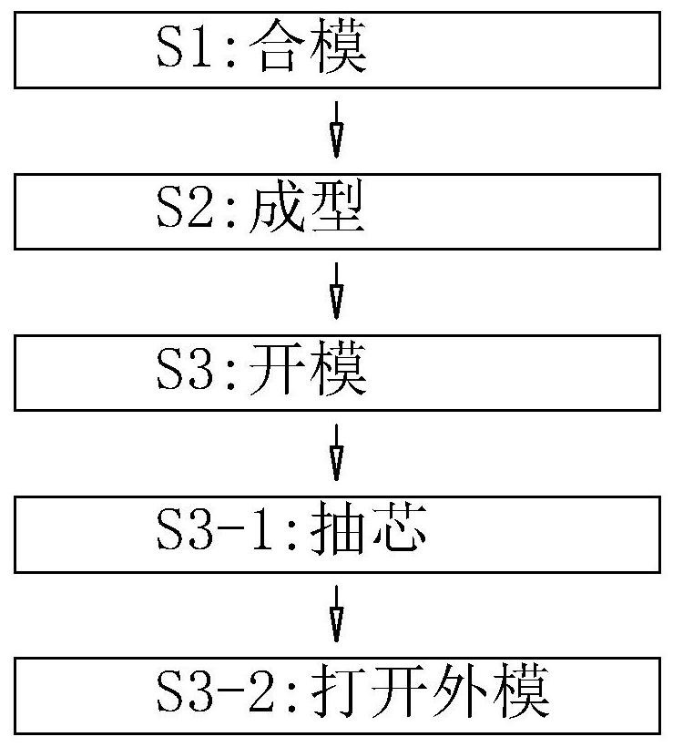
[0053] The embodiment of the present application discloses a mold opening method of a core shooter. refer to figure 1 , the core making and mold opening method of the core shooter includes the following steps:

[0054] S1: Mold closing, splicing the lower mold, upper mold, outer mold and core mold together, forming a cavity between the lower mold, upper mold, outer mold and core mold;

[0055] S2: Molding, spraying the core sand into the mold cavity, and passing triethylamine gas into the mold cavity, the core sand forms strength under the catalysis of triethylamine gas, so that the core sand aggregates into a sand core;

[0056] S3: open the mold, open the upper mold, core mold and outer mold;

[0057] Among them, S3 also includes S3-1: core pulling and S3-2 opening the outer mold;

[0058] S3-1: Core pulling, remove the upper mold and pull out the core mold from the sand core, and both the upper mold and the core mold slide along their own axial direction away from the lo...

Embodiment 2

[0068] The embodiment of the present application discloses a mold opening method of a core shooter. The difference from Embodiment 1 is that in S3-1: core pulling, the upper mold is removed and the core mold is pulled out from the sand core, the upper mold slides along the axial direction of the core mold away from the lower mold, and the core mold All slide along their own axial direction away from the upper die under the guide;

[0069] S3-2: Open the outer mold, the outer mold includes the first half mold, the second half mold, the third half mold and the fourth half mold, the first half mold, the second half mold, the third half mold and the fourth half mold The molds all slide towards the side away from the mandrel along the direction perpendicular to the axis of the mandrel.

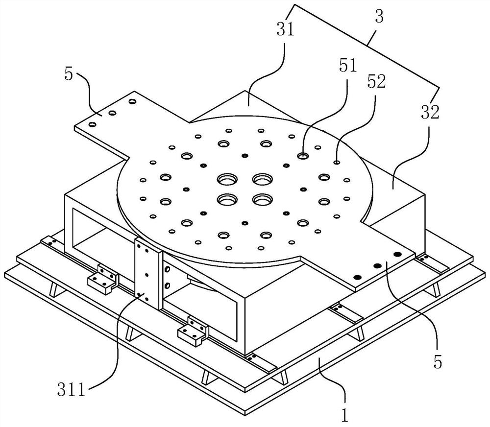
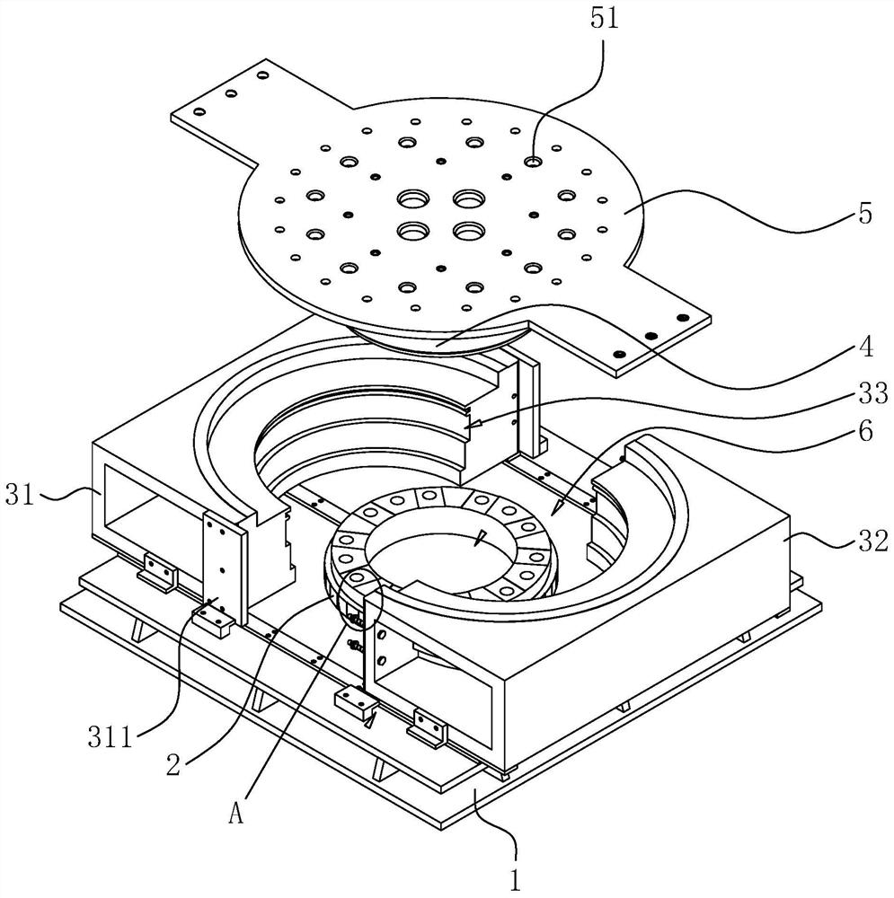
[0070] The embodiment of the present application also discloses a core box using the above mold opening method, referring to Image 6 , The core box includes a base 1, a lower mold 2, an outer mo...


PUM


Abstract

The invention relates to a die opening method of a core shooter, and relates to the technical field of spheroidal graphite cast iron pipe core making. The die opening method of the core shooter comprises the steps of S1, carrying out die closing; S2, forming; and S3, carrying out die opening, wherein the step S3 further comprises the steps of S3-1, carrying out core-pulling: moving an upper die away, and pulling a core die out from a sand core along the axial direction of a lower die; and S3-2, opening an outer die: separating the outer die from the sand core. According to the die opening method of the core shooter provided by the invention, after core sand produces strength and forms the sand core, the upper die is firstly moved away, then the core die is pulled out from the sand core along the axial direction of the lower die, the peripheral face of the sand core is protected by the outer die at the moment, the sand core is not easy to damage when the core die is pulled out from thesand core, then the outer die is opened, and the sand core is not needed to be moved in the die opening process, so that the probability of sand core damage is reduced, the sand core precision is improved, and the precision of a female end of a spheroidal graphite cast iron pipe is further improved.

Description

technical field [0001] The application relates to the technical field of ductile iron tube cores, in particular to a mold opening method for a core shooter. Background technique [0002] In order to form the internal shape of the socket end of the ductile iron pipe, a sand core needs to be placed inside the socket end of the pipe mold. Every time a ductile iron pipe is poured, a sand core needs to be consumed. The cavity inside the socket end of the pipe mold and the outside of the sand core The socket end of the ductile iron pipe is formed between them. [0003] Sand cores are mostly made by core making machines and core boxes. Most core boxes include lower molds, upper molds, outer molds and core molds. Most of the current core-making and mold-opening methods include the following steps: [0004] S1: Mold closing, splicing the lower mold, upper mold, outer mold and core mold together, forming a cavity between the lower mold, upper mold, outer mold and core mold; [0005]...

Claims


Application Information

Patent Timeline
Patent Type & Authority Applications(China)
IPC IPC(8): B22C15/24B22C13/12
CPCB22C13/12B22C15/24
Inventor 柳玉川莫贻贵訾陆坤柳嵩
Owner 济南柳玉鑫机械设备有限公司
Why Eureka
Try Eureka