
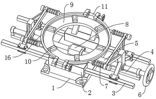
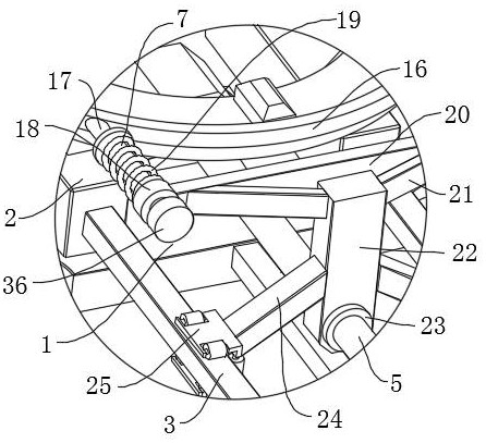
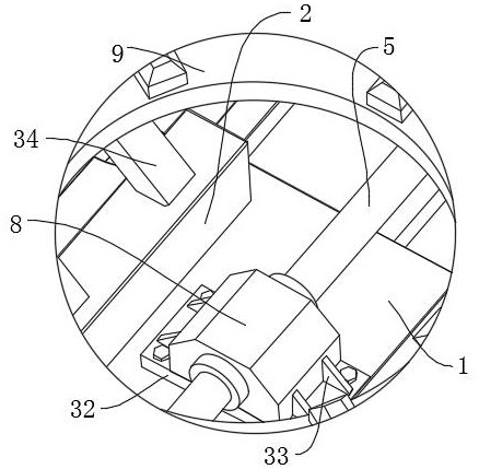
Special fixture for cylindrical bearing retainer

A special fixture and cylindrical bearing technology, which is applied in the direction of manufacturing tools, grinding workpiece brackets, metal processing equipment, etc., can solve the problems of poor protection of the cage, high clamping force of the cage, deformation of the cage, etc., to improve clamping The effect of holding convenience, improving protection and reducing friction

Active Publication Date: 2022-08-05
SHANDONG GOLDEN EMPIRE PRECISION MACHINERY TECH CO LTD
View PDF5 Cites 1 Cited by
  • Summary
  • Abstract
  • Description
  • Claims
  • Application Information

AI Technical Summary

Problems solved by technology

Its main function is to support the mechanical rotating body, reduce the friction coefficient during its movement, and ensure its rotation accuracy. The cylindrical bearing cage needs to be clamped by a fixture when it is grinding the end face. However, the existing In the process of clamping with clamps, because the strength of the clamps is not easy to control, it is easy to cause excessive clamping force on the cage during the clamping process, and then the cage is caused by excessive clamping force. The phenomenon of deformation, that is, the protection of the cage is poor when clamping

Method used


Image

  • Special fixture for cylindrical bearing retainer
  • Special fixture for cylindrical bearing retainer
  • Special fixture for cylindrical bearing retainer

Examples


Embodiment Construction

[0023] The following description serves to disclose the invention to enable those skilled in the art to practice the invention. The preferred embodiments described below are given by way of example only, and other obvious modifications will occur to those skilled in the art.

[0024] like Figure 1-Figure 6 A special clamp for a cylindrical bearing cage is shown, including a clamp base 1, a pusher is installed in the middle of the upper end of the clamp base 1, a clamp is connected to the end of the pusher, and a top piece is installed at the upper edge of the clamp base 1. , the axis line of the top piece is collinear with the axis line of the clamping piece, the corner of the upper end face of the clamping base 1 is provided with a mounting hole, and the top piece is connected with the pushing piece.

[0025] The pusher includes a threaded rod 5 installed in the middle of the upper end of the clamp base 1. The threads at both ends of the threaded rod 5 are symmetrically arr...


PUM


Abstract

The invention relates to the field of bearing production, in particular to a special fixture for a cylindrical bearing retainer, which comprises a clamping seat, a pushing part is mounted in the middle of the upper end of the clamping seat, a clamping part is connected to the end part of the pushing part, an ejection part is mounted at the edge of the upper end of the clamping seat, and the axis of the ejection part and the axis of the clamping part are collinear. Mounting holes are formed in the corners of the upper end face of the clamping base in a penetrating mode, and the ejecting piece is connected with the pushing piece. According to the holder clamping device, the convenience degree of holder clamping can be improved, it can be guaranteed that more labor is saved during clamping, and the protection force on the holder during clamping and the clamping stability can be improved.

Description

technical field [0001] The invention relates to the field of bearing production, in particular to a special clamp for a cylindrical bearing cage. Background technique [0002] Bearings are an important component in contemporary machinery and equipment. Its main function is to support the mechanical rotating body, reduce the friction coefficient during its movement, and ensure its rotation accuracy. Among them, the cylindrical bearing cage needs to be clamped by a clamp when grinding the end face. However, the existing In the process of using clamps for clamping, because the force of the clamps is not easy to control, the phenomenon of excessive clamping force on the cage is prone to occur during the clamping process, and then the cage is caused by excessive clamping force. The phenomenon of deformation, that is, the protection of the cage during clamping is poor. SUMMARY OF THE INVENTION [0003] The purpose of the present invention is to propose a special clamp for a cy...

Claims


Application Information

Patent Timeline
Patent Type & Authority Applications(China)
IPC IPC(8): B24B19/00B24B41/06B24B47/22
CPCB24B19/00B24B41/06B24B47/22
Inventor 郑广会赵培振郑世育
Owner SHANDONG GOLDEN EMPIRE PRECISION MACHINERY TECH CO LTD
Learn More