Anti-deformation device for sealing ring assembly and using method
A sealing ring, anti-deformation technology, used in shafts and bearings, bearing components, manufacturing tools, etc., can solve the problems of continuous stamping assembly, sealing ring positioning, bearing deformation, etc., to avoid deformation, increase sealing, improve The effect of precision
- Summary
- Abstract
- Description
- Claims
- Application Information
AI Technical Summary
Problems solved by technology
Method used
Image
Examples
Embodiment 1
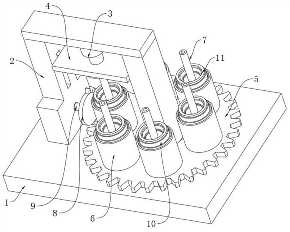
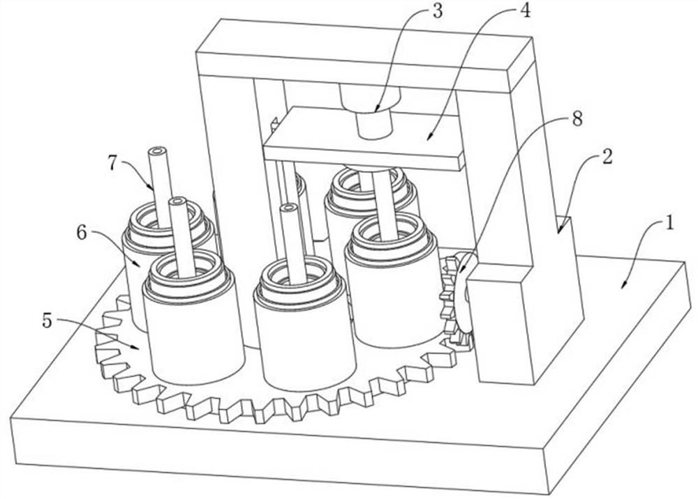
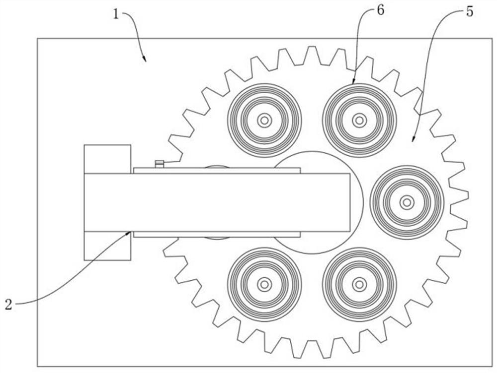
[0041] like figure 1 , Image 6 , Figure 7 and Figure 9 As shown, an anti-deformation device for assembling a sealing ring includes a base 1, a frame 2 is fixedly installed on the base 1, a gear ring 5 is rotatably installed on the upper surface of the base 1, and no less than six An assembly seat 6 is placed on the assembly seat 6, a bearing 10 is placed on the assembly seat 6, a sealing ring 11 is placed on the upper end of the bearing 10, a hydraulic cylinder 3 is fixedly installed on the inner top of the frame 2, and the extension end of the hydraulic cylinder 3 is fixedly connected with a pressure plate 4, and the pressure plate 4 is two Both ends are fixedly connected with the slider 25, the frame 2 is provided with a chute matching the slider 25, and the assembly seat 6 is provided with a negative pressure positioning mechanism;
[0042] The negative pressure positioning mechanism includes a piston cavity arranged inside the assembly seat 6 , a second piston plate ...
Embodiment 2
[0046] like Figure 7 and Figure 9 As shown, the assembly seat 6 is provided with an annular positioning seat 27, the bearing 10 is placed inside the annular positioning seat 27, and an inflation airbag 26 is provided on both inner side walls of the annular positioning seat 27, and the inflation airbag 26 is in contact with both sides of the bearing 10; The inside of the piston cavity is provided with a first piston plate 15, the first piston plate 15 is located below the second piston plate 17, one side of the piston cavity is connected with an air pipe 24, and one end of the air pipe 24 is connected to the first piston plate 15 and the second piston plate 17. The cavity formed between them is connected internally, and the other end of the gas delivery pipe 24 is connected with the inside of the inflation airbag 26; during the working process, when the second piston plate 17 moves down under the action of pressure, at this time, the second piston plate 17 can be connected to...
Embodiment 3
[0048] like Figure 7 , Figure 8 and Figure 10 As shown, a return spring is provided between the lower surface of the first piston plate 15 and the inner bottom end of the piston cavity, a fixed air pipe 16 is fixedly installed on the first piston plate 15, the bottom end of the fixed air pipe 16 is communicated with the interior of the piston cavity, and the fixed air pipe 16 The top end extends to the inside of the piston tube 7 and is slidably connected to the piston tube 7; the lower surface of the pressure plate 4 is provided with an annular seat 12, an annular air pipe 18 is arranged inside the annular seat 12, and a circular limit seat 19 is arranged in the center of the annular seat 12. The inner limit seat 19 is provided with a limit cavity 20 matched with the piston tube 7, the limit cavity 20 is communicated with the inside of the annular gas pipe 18 through a pipeline, and an exhaust port 21 is provided on the lower surface of the annular seat 12, and the exhaus...
PUM
 Abstract
Description
Claims
Application Information
 - R&D
- Intellectual Property
- Life Sciences
- Materials
- Tech Scout
- Unparalleled Data Quality
- Higher Quality Content
- 60% Fewer Hallucinations
Browse by: Latest US Patents, China's latest patents, Technical Efficacy Thesaurus, Application Domain, Technology Topic, Popular Technical Reports.
© 2025 PatSnap. All rights reserved.Legal|Privacy policy|Modern Slavery Act Transparency Statement|Sitemap|About US| Contact US: help@patsnap.com


