Real-time dynamic monitoring equipment and real-time dynamic monitoring method for engineering cost

A monitoring equipment, real-time dynamic technology, applied in the direction of mechanical equipment, machine/support, supporting machine, etc., can solve the problems of difficult construction site shooting, inconvenient to adjust the camera angle of monitoring equipment, etc.

Inactive Publication Date: 2022-08-09
陈玉敏 +4
View PDF0 Cites 0 Cited by
  • Summary
  • Abstract
  • Description
  • Claims
  • Application Information

AI Technical Summary

Problems solved by technology

[0004] In view of the above situation, in order to overcome the defects of the prior art, the present invention provides a real-time dynamic monitoring equipment and real-time dynamic monitoring method for engineering cost, which effectively solves the problem that the monitoring equipment for engineering cost management in the above-mentioned background technology is directly fixed and installed at a designated location. It is inconvenient to adjust the camera angle of the monitoring equipment, which makes it difficult to accurately shoot the construction site, and there are certain limitations

Method used


Image

  • Real-time dynamic monitoring equipment and real-time dynamic monitoring method for engineering cost
  • Real-time dynamic monitoring equipment and real-time dynamic monitoring method for engineering cost
  • Real-time dynamic monitoring equipment and real-time dynamic monitoring method for engineering cost

Examples


Embodiment 1

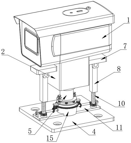
[0039] Example one, by Figure 1 to Figure 9 Given, the present invention includes a monitoring device body 1, the bottom of the monitoring device body 1 is fixedly connected with a fixed block 2, the bottom of the fixed block 2 is provided with a spherical groove 3, and a fixed seat 4 is arranged below the fixed block 2, and the bottom of the fixed seat 4 is provided. The top is fixedly connected with a support column 5, the top of the support column 5 is provided with a fixing ball 6, both sides of the fixing block 2 are fixedly connected with a first fixing plate 7, and a lifting plate 8 is arranged below the first fixing plate 7. The lifting plate 8 and the first fixing plate 7 are connected by a rotary slider, the bottom of the lifting plate 8 is provided with a threaded groove 9, the threaded groove 9 is provided with a first lead screw 10, and the fixed seat 4 is provided with a matching first lead screw 10. multi-directional monitoring and adjustment components;

[00...

Embodiment 2

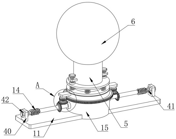
[0041] The second embodiment, on the basis of the first embodiment, is composed of figure 2 , image 3 and Image 6 Given, the synchronous rotation mechanism includes a first bevel gear 19 sleeved on the outside of the worm 14, the first bevel gear 19 is fixedly connected with the worm 14, a second bevel gear 20 is arranged above the worm 14, and the fixed sleeve 15 is on the Two second fixing plates 22 are fixedly connected, a rotating shaft 21 is arranged below the second fixing plate 22, the bottom end of the rotating shaft 21 is fixedly connected with the second bevel gear 20, and the top end of the rotating shaft 21 and the second fixing plate 22 pass through the second fixed plate 22. The three bearings 23 are connected, a first gear ring 24 is sleeved on the outside of the rotating shaft 21, the first gear ring 24 is fixedly connected with the rotating shaft 21, and the two first gear rings 24 are connected by a gear driver. The outer second gear ring 25, the second ...

Embodiment 3

[0042] Embodiment 3, on the basis of Embodiment 1, by figure 1 , figure 2 , Figure 4 and Figure 8 Given, the rotary slider includes a slider 28 arranged at the top of the lifting plate 8, the bottom of the first fixed plate 7 is provided with a chute 27, both sides of the lifting plate 8 are provided with side plates 29, the side plates 29 and the slider 28 is fixedly connected, and the side plate 29 and the lifting plate 8 are rotatably connected, the slider 28 is located in the chute 27, the cross-sections of the chute 27 and the slider 28 are T-shaped structures, and the fixed ball 6 is located in the spherical groove 3;

[0043] The two worms 14 are driven to rotate in opposite directions, so that the worms 14 drive the worm wheel 13 to rotate, and then the first lead screw 10 is driven to rotate through the worm wheel 13, so that the two first lead screws 10 rotate in opposite directions. The cooperation of the threaded grooves 9 changes the height of the lifting pl...


PUM


Abstract

The invention relates to the technical field of project cost management, discloses project cost real-time dynamic monitoring equipment and a real-time dynamic monitoring method, and solves the problems that the monitoring equipment for project cost management is directly and fixedly mounted at a specified position, the shooting angle of the monitoring equipment is inconvenient to adjust, a construction site is difficult to shoot accurately, and the construction cost is low. The monitoring device comprises a monitoring device body, the bottom of the monitoring device body is fixedly connected with a fixing block, the bottom of the fixing block is provided with a spherical groove, a fixing seat is arranged below the fixing block, the top of the fixing seat is fixedly connected with a supporting column, and the top end of the supporting column is provided with a fixing ball. First fixing plates are fixedly connected to the two sides of the fixing block, lifting plates are arranged below the first fixing plates, and the lifting plates and the first fixing plates are connected through rotary sliders; the monitoring position of the monitoring equipment body can be adjusted in multiple directions, and a construction site can be accurately shot.

Description

technical field [0001] The invention belongs to the technical field of engineering cost management, in particular to a real-time dynamic monitoring device and a real-time dynamic monitoring method for engineering cost. Background technique [0002] Project cost management is the use of scientific and technical principles and methods, under the principle of unified goals and each responsible, in order to ensure the economic benefits of construction projects and the economic rights and interests of all parties concerned. During the construction process, the progress of the project should be followed up at all times in order to understand the real-time situation. At this time, it is necessary to use monitoring equipment for real-time dynamic follow-up. [0003] In the prior art, the monitoring equipment for project cost management is directly and fixedly installed in a designated position, and it is inconvenient to adjust the camera angle of the monitoring equipment, which make...

Claims


Application Information

Patent Timeline
Patent Type & Authority Applications(China)
IPC IPC(8): F16M11/06F16M11/18F16M13/02
CPCF16M11/06F16M11/18F16M13/02
Inventor 陈玉敏李玉杰夏亚杰曹源白雪菊
Owner 陈玉敏
Why Eureka
Try Eureka