Artificial intelligence real-time monitoring device

A technology of real-time monitoring and artificial intelligence, which is applied to the transmission device, the cleaning method using tools, and the body of the camera, etc., can solve the problems of monitoring dead angle, slow response speed, and visual blind spots, so as to achieve fast response speed and avoid monitoring The effect of dead ends

Active Publication Date: 2022-08-09
扬州市职业大学(扬州开放大学)
View PDF7 Cites 0 Cited by
  • Summary
  • Abstract
  • Description
  • Claims
  • Application Information

AI Technical Summary

Problems solved by technology

However, because the monitoring angle of view of the monitoring camera is rated, when a full range of 360° monitoring is required, multiple monitoring cameras are required for monitoring. However, the current monitoring device can complete all-round monitoring through the cooperation of multiple cameras , there will still be visual blind spots at the framing boundaries of each surveillance camera, especially near the corners of the cameras, resulting in dead spots in surveillance
At the same time, during the monitoring process, when dust appears on the surface of the camera, the current cleaning of the camera is generally done manually, and the response speed is slow

Method used


Image

  • Artificial intelligence real-time monitoring device
  • Artificial intelligence real-time monitoring device
  • Artificial intelligence real-time monitoring device

Examples


Embodiment Construction

[0029] The technical solutions in the embodiments of the present invention will be clearly and completely described below with reference to the accompanying drawings in the embodiments of the present invention. Obviously, the described embodiments are only a part of the embodiments of the present invention, but not all of the embodiments.

[0030] In the description of the present invention, it should be understood that the terms "upper", "lower", "front", "rear", "left", "right", "top", "bottom", "inside", " The orientation or positional relationship indicated by "outside" is based on the orientation or positional relationship shown in the accompanying drawings, and is only for the convenience of describing the present invention and simplifying the description, rather than indicating or implying that the indicated device or element must have a specific orientation, so as to The specific orientation configuration and operation are therefore not to be construed as limitations of...


PUM


Abstract

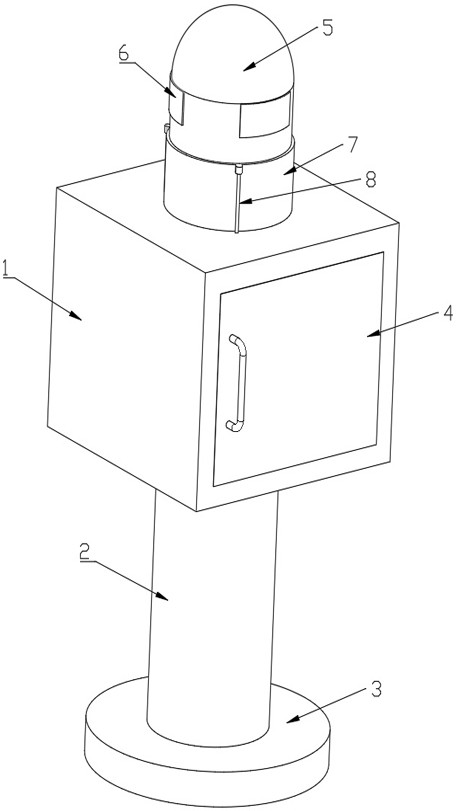
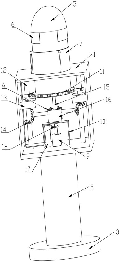
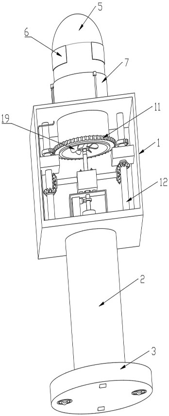
The invention discloses an artificial intelligence real-time monitoring device, and relates to the technical field of monitoring, the artificial intelligence real-time monitoring device comprises a monitoring main box body and a mobile base, the top surface of the mobile base is fixedly connected with a lifting column for supporting and adjusting lifting of the monitoring main box body, and the top end of the monitoring main box body is rotatably provided with a hollow rotary monitoring column; a plurality of monitoring cameras are installed on the surface of the top end of the rotating monitoring column, a motor is fixedly installed on the bottom wall in the monitoring main box body, a U-shaped frame is installed above the motor, a rotating shaft is connected to an output shaft of the motor, and a transmission mechanism located on the outer side of the rotating shaft is arranged at the top end of the U-shaped frame and used for driving the rotating monitoring column to rotate. The device further comprises a cleaning plate capable of cleaning the rotary monitoring column. In the real-time monitoring process of the monitoring camera, no monitoring dead angle is ensured, the cleaning requirement can be responded in time, and the monitoring definition is ensured.

Description

technical field [0001] The invention relates to the technical field of monitoring equipment, in particular to an artificial intelligence real-time monitoring device. Background technique [0002] Monitoring equipment mainly records abnormal events in the area, which plays a role in monitoring and facilitating post-event tracing. With the continuous development of society, the role of monitoring in life is becoming more and more obvious. At present, monitoring equipment is widely used. In various fields such as life and scientific research, and with the rapid development of the Internet, the traditional system monitoring method is mainly realized by relying on technicians to manually set different applications and different machines, which undoubtedly increases the workload of personnel and greatly reduces monitoring. Therefore, the use of artificial intelligence to replace manual monitoring is more and more widely used. [0003] Real-time monitoring of monitoring areas (suc...

Claims


Application Information

Patent Timeline
Patent Type & Authority Applications(China)
IPC IPC(8): F16M11/08F16M11/18F16M11/42F16H27/02F16D28/00H04N7/18H04N5/232H04N5/225G03B17/55B08B1/00B08B1/02
CPCF16M11/08F16M11/18F16M11/42F16H27/02F16D28/00H04N7/18G03B17/55B08B1/006B08B1/02H04N23/50H04N23/695
Inventor 江兆银
Owner 扬州市职业大学(扬州开放大学)
Why Eureka
Try Eureka