
Directional navigation within a graphical user interface

A graphical user interface and vector technology, applied in the direction of image communication, selective content distribution, color TV parts, etc., can solve low efficiency and other problems

Inactive Publication Date: 2004-06-09
KONINKLIJKE PHILIPS ELECTRONICS NV
View PDF7 Cites 0 Cited by
  • Summary
  • Abstract
  • Description
  • Claims
  • Application Information

AI Technical Summary

Problems solved by technology

[0004] There is a deficiency in this prior art device and method due to the relative inefficiency caused by calculating the weighted distance for each of the remaining controls

Method used


Image

  • Directional navigation within a graphical user interface
  • Directional navigation within a graphical user interface
  • Directional navigation within a graphical user interface

Examples


Embodiment Construction

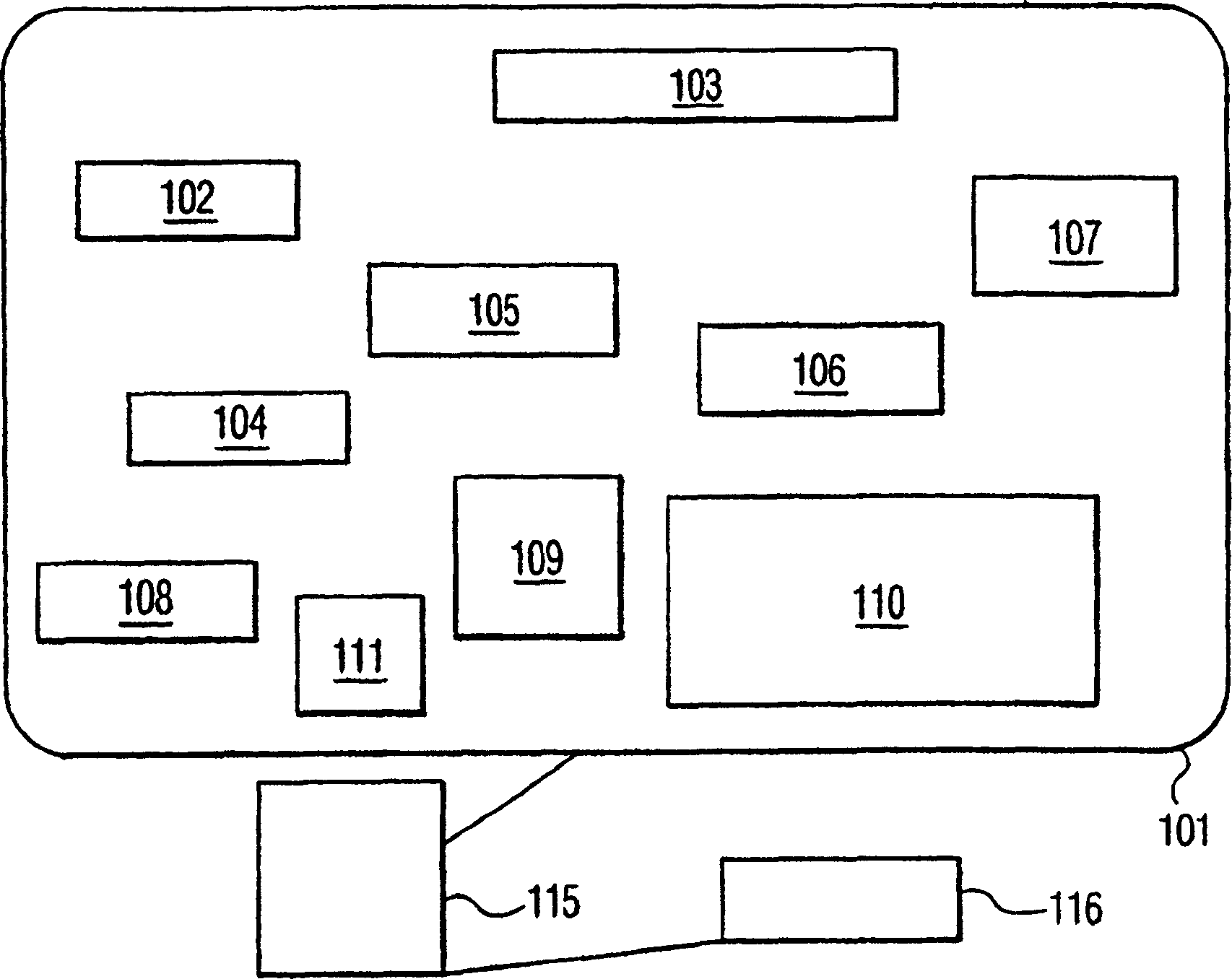
[0033] figure 1 The principle of a menu for an Internet access interface based TV is shown. The television screen 101 displays a plurality of menu items 102-111. Each menu item is associated with a multi-pixel field or target area on the display. Menu items are available in a regular table arrangement or in an irregular arrangement. Typically, menu items are displayed as boxes, positions, or fields on the screen. All boxes can be the same size or different, depending on the needs of the application. For the purposes of the above application the terms "menu item", "menu element" and "menu option" are used without distinction. The television screen is connected to the processor 115; the processor may be a set-top box or an internal processor. The processor interfaces with device 116 to receive remote control input. Device 116 may be a remote IR (infrared) sensor.

[0034] figure 1 It is only possible to utilize the principles of one data processing system of the invent...


PUM


Abstract

In a graphical user interface, preferably for use with a television and set top box, menu navigation is achieved through use of a directional input. From the directional input and a current position, a fitness measure is derived for each menu option. From the fitness measure, a processing device guesses a target menu location. The directional input typically will come from a remote with buttons indicating directions, including diagonal directions.

Description

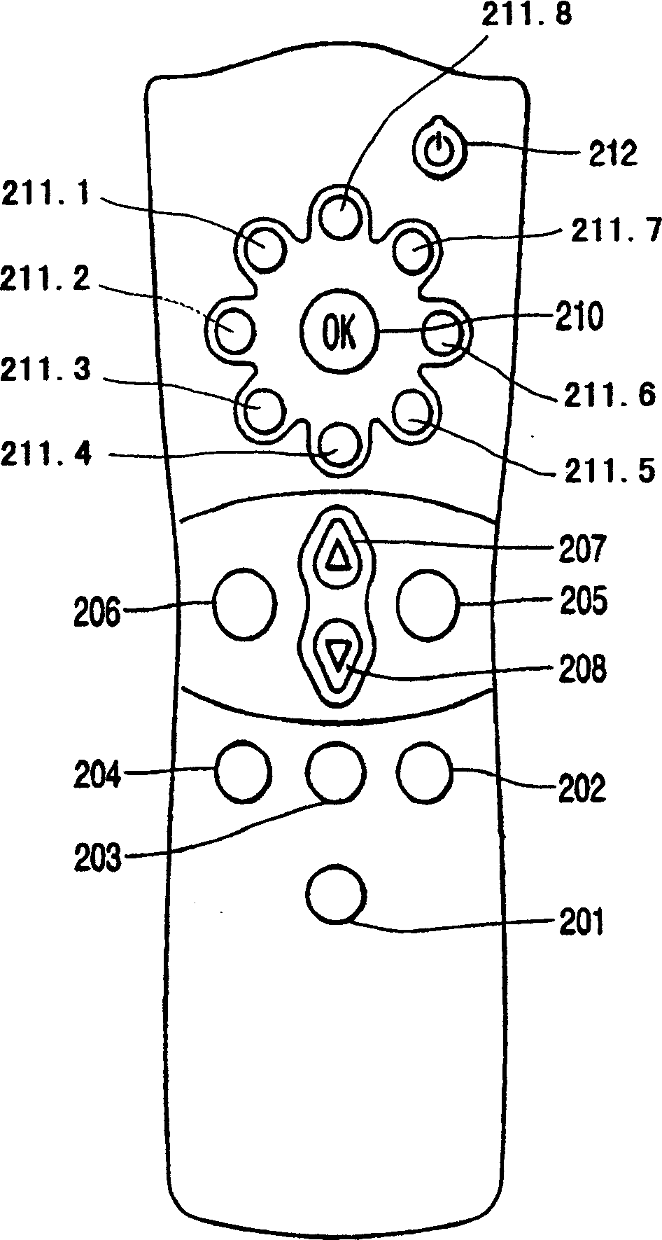
technical field [0001] The invention relates to the field of Graphical User Interfaces (GUI), and in particular to directional navigation in such interfaces. Background technique [0002] In particular, directional navigation in GUIs has been problematic in the field of television-based Internet access set-top boxes such as Internet TV. Menus for such systems are sometimes displayed as boxes or positions to be selected on the television screen. Typically, the user navigates with a remote control rather than with a mouse or trackball. Typically, remote controls have relatively rudimentary directions such as buttons with arrows pointing up, down, right and left, see e.g. image 3 PCT application WO 98 / 43 381. Sometimes the interpretation of these arrows by the set-top box is flawed, and the directional commands give a certain direction rather than what the user wishes. [0003] A prior art system and method is known from EP 0 671 682 A2 which discloses an apparatus and meth...

Claims


Application Information

Patent Timeline
Patent Type & Authority Patents(China)
IPC IPC(8): G06F3/033G06F3/0481G06F3/0484G06F9/44G08B13/196G08B25/08H04L29/08H04L29/12H04N5/445
CPCH04L67/08H04L29/08981H04L69/329H04L29/08126G08B13/19682G06F3/04812H04L67/34G08B25/08H04N5/44591H04L29/12047H04L67/12H04L61/15H04N21/4316H04L29/08558H04N21/47H04L29/12009H04N21/4438H04L29/08072H04L67/303H04N21/25808H04N21/2662G06F3/04842H04L29/08927H04N21/42204H04N21/4221H04L61/45H04L61/00H04N21/431
Inventor M·奎佩尔斯J·范埃
Owner KONINKLIJKE PHILIPS ELECTRONICS NV
Learn More