Check patentability & draft patents in minutes with Patsnap Eureka AI!

Fin-type heat exchanger

A technology of heat exchangers and fins, applied in the field of finned heat exchangers, can solve problems such as uneven air, increased manufacturing costs, and complicated manufacturing processes

Inactive Publication Date: 2004-06-30
SAMSUNG ELECTRONICS CO LTD
View PDF1 Cites 1 Cited by
  • Summary
  • Abstract
  • Description
  • Claims
  • Application Information

AI Technical Summary

Problems solved by technology

Consequently, the air is very unevenly crossed over the surface of the fins 12 in this region, and the large volume of air passing through these two components creates noise.
[0014] Finally, because the slits 14 formed between the tube holes 13a of the first row 12a are located on both sides of the fins 12, the manufacturing process is complicated and the overall manufacturing cost increases.

Method used


Image

  • Fin-type heat exchanger
  • Fin-type heat exchanger
  • Fin-type heat exchanger

Examples


Embodiment Construction

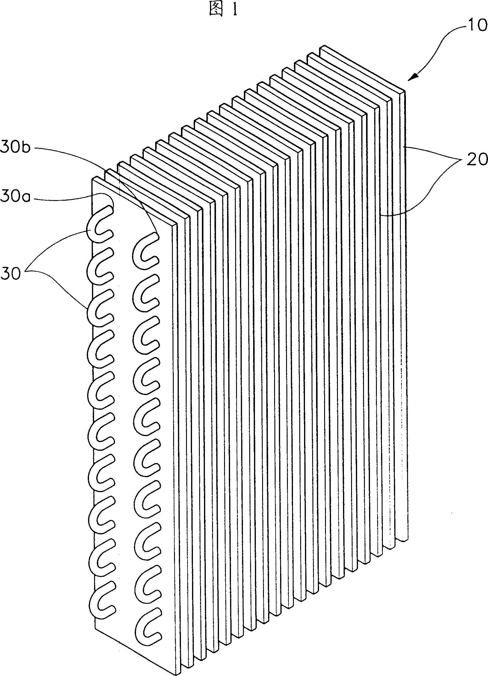
[0027] A preferred embodiment of the present invention will now be described with reference to the accompanying drawings.

[0028] Referring first to Figure 1, there is shown a perspective view of a finned heat exchanger 10 of the present invention. The heat exchanger 10 includes a plurality of plate-shaped fins 20 arranged parallel to each other at predetermined intervals, the fins 20 having at least two rows of tube holes 30a and 30b formed along the length of the fins 20 at predetermined intervals, one tube 30 Inserted into the tube holes 30 a and 30 b by bending on the outside of the heat exchanger 10 . Refrigerant or other working fluid passes through the tubes 30, exchanging heat with the air across the outer surfaces of the tubes 30 and fins 20, which act as an intermediary.

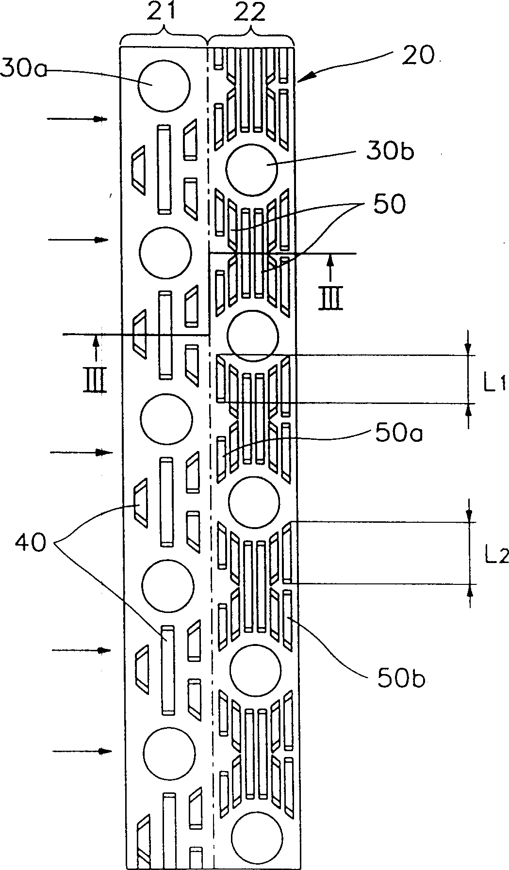
[0029] figure 2 It is a plan view of one of the fins 20 shown in Fig. 1, as shown in the figure, the fin 20 is divided into two sides: a suction side 21, on this side, the tube holes 30a form a...


PUM


Abstract

A fin type heat exchanger includes a plurality of plate shaped fins disposed in spaced parallel; pipe holes formed in the preconcerted space along the length; a pipe bended a plurality of times to insert into the pipe holes; slits formed in row in the preconcerted pattern on the outsiad of the fin. Each fin, whereby there is a first row of slit groups adjacent the air intake side, and a second row of slit groups adjacent the air exhaust side. There are more slits in the first row than in the second row. The slits in the first row have a width greater than the width of the slits disposed in the second row.

Description

technical field [0001] The present invention relates to a finned heat exchanger, in particular to the finned heat exchanger which improves the arrangement of the slits formed on the fins, improves the heat exchange efficiency and reduces the noise. Background technique [0002] The structure of a general fin type heat exchanger includes a tube bent multiple times, and the fins are parallel to each other at predetermined intervals, and the tube passes through the fins. Such a heat exchanger is used in an air conditioner or the like to exchange heat between the outside air passing over the fins and the outer surface of the tubes and the working fluid flowing through the tubes. [0003] The fins receive heat from the tubes, exchanging heat with the surrounding air. That is, the heat from the tube is transferred to the fin, so that the heat transfer area is greatly increased. To further enhance this function, multiple cutouts protrude from the surface of each fin. These cuts ...

Claims


Application Information

Patent Timeline
Patent Type & Authority Patents(China)
IPC IPC(8): F28D1/047F28F1/32
CPCF28D1/0477F28F1/325
Inventor 郑圭夏裴泳潡郑圣翰
Owner SAMSUNG ELECTRONICS CO LTD
Features
  • R&D
  • Intellectual Property
  • Life Sciences
  • Materials
  • Tech Scout
  • Unparalleled Data Quality
  • Higher Quality Content
  • 60% Fewer Hallucinations
Learn More