Heat regenerator of original surface for gas turbine

A gas turbine and regenerator technology, which is applied in gas turbine installations, machines/engines, mechanical equipment, etc., can solve the problem of reduced heat exchange effect, large difference in flow velocity, undetermined ratio of air and gas flow passages on both sides, etc. problems, to achieve the effect of improving service life, high heat exchange efficiency, and good compactness

Inactive Publication Date: 2005-01-05
XI AN JIAOTONG UNIV
View PDF0 Cites 25 Cited by
  • Summary
  • Abstract
  • Description
  • Claims
  • Application Information

AI Technical Summary

Problems solved by technology

In addition, as the pressure loss increases, the regenerator is prone to fouling and blockage
[0009] For the regenerator with CC surface, the cross-sectional area of ​​the gas side and the air side flow channel are equal, which means that when the volume flow on both sides is similar, the heat transfer effect is better, but if the volume flow difference on both sides is large, such as in a micro gas turbine The difference between the volume flow rate of gas and air on both sides is more than three times, the difference in flow velocity is large, and the heat transfer effect is obviously reduced
[0010] For the improved CC surface in the prior art, only the corrugated shape of this surface has been improved, and the ratio of the cross-sectional area of ​​the flow channels on both sides of the air and gas formed on this surface has not been determined, and how to improve this surface has not been determined. Only in this way can the heat exchange effect of the media on both sides of the regenerator be the best

Method used


Image

  • Heat regenerator of original surface for gas turbine
  • Heat regenerator of original surface for gas turbine
  • Heat regenerator of original surface for gas turbine

Examples


Embodiment Construction

[0030] Accompanying drawing is the specific embodiment of the present invention.

[0031] Below in conjunction with accompanying drawing, the specific content of the present invention is described in further detail:

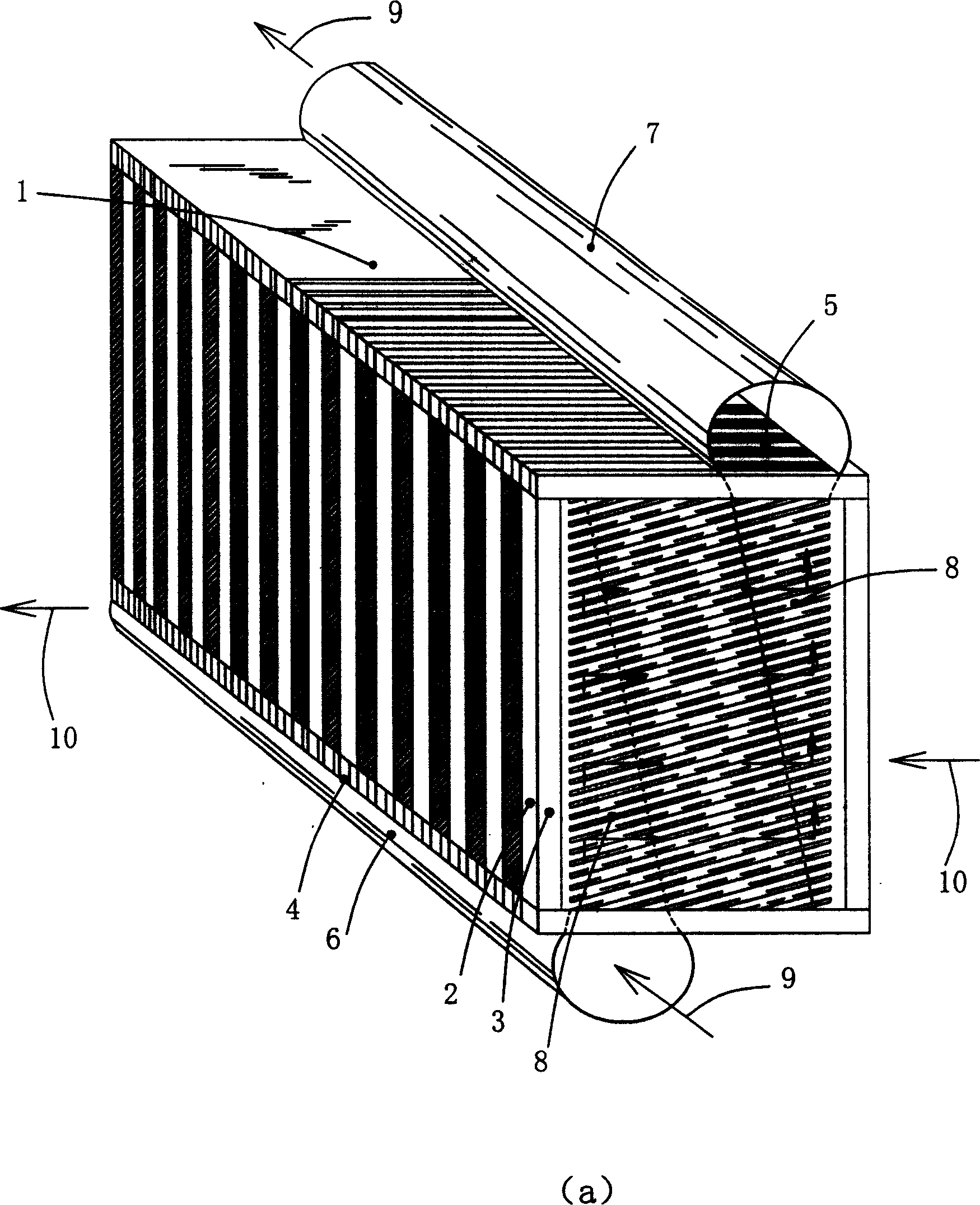
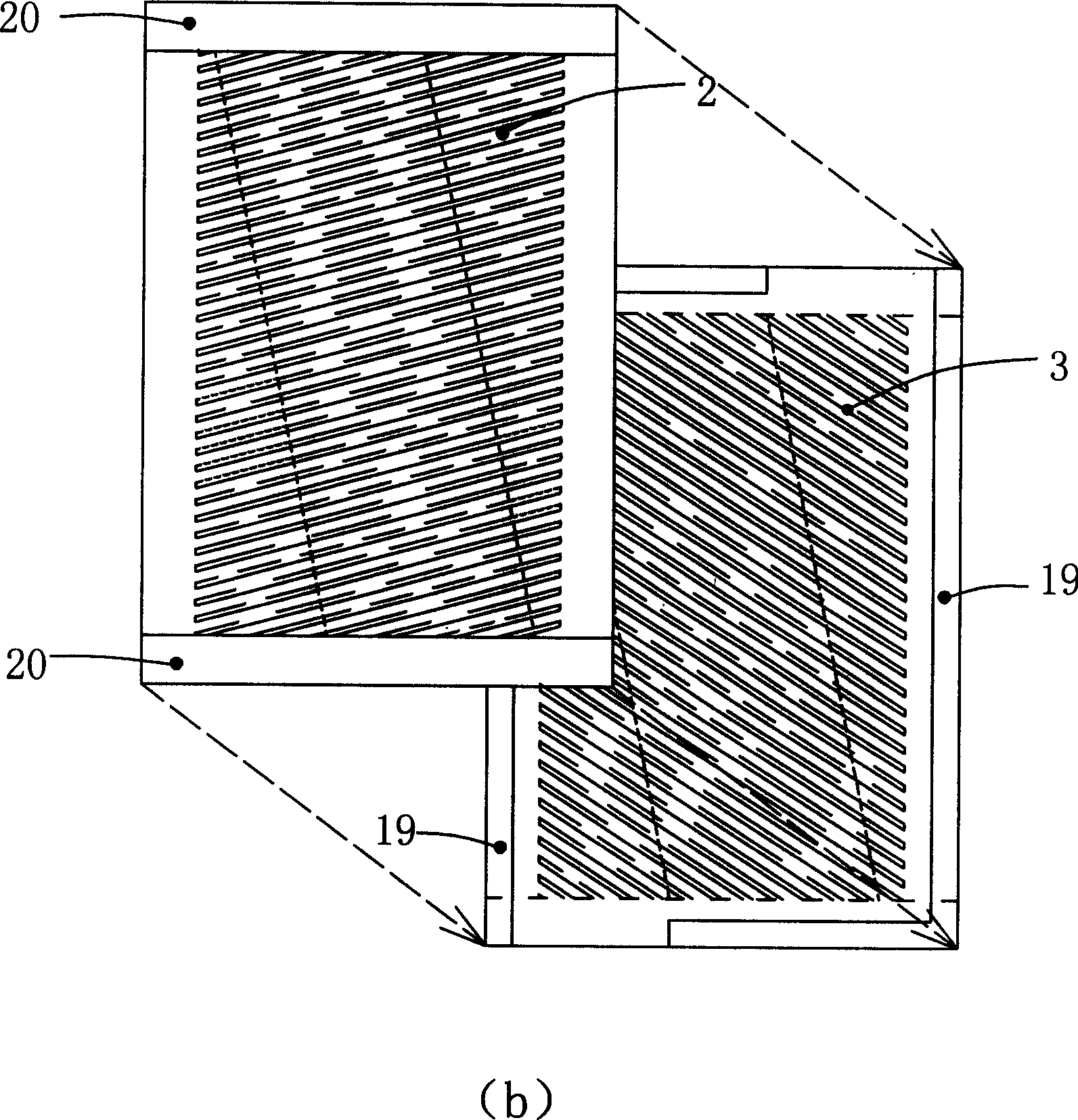
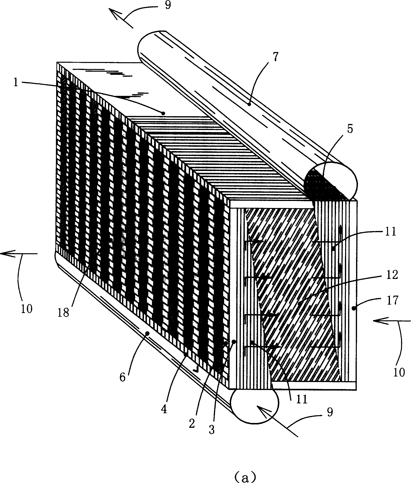
[0032] refer to figure 2 As shown in (a), the original surface regenerator is composed of the main body 1 welded with the air inlet and outlet circular channels 6, 7, the main body 1 is formed by welding together a plurality of heat exchange plates 2, 3, and the heat exchange plates are formed when welding Air inlet and outlet 4, 5, air inlet and outlet circular channels 6, 7 are respectively parallel to air inlet 4 and air outlet 5, and are respectively welded on two opposite corners of the regenerator, and the air flows along the direction shown in 9 Enter the port 4, enter the heat exchange corrugated area 12 through the deflector 11, and then lead out of the main body 1 along the other side of the deflector 11, and flow out of the regenerator along the air ...


PUM


Abstract

The invention relates to a regenerator for a micro gas turbine, concretely is a original surface heat exchanger for increasing the heat efficiency of the gas turbine, it can increase the compactness and the service life of regenerator. The gas inlet and outlet channels are arranged on the right lower horn and the left upper horn, the high pressure air flows into the regenerator through the air inlet channel, flows out from the air outlet channel, the left and right frames of the heat exchanging board are welded and formed a air in/out aperture, the fuel gas can flow into the regenerator through the aperture, flows out form aperture on another side, the centre is heat exchanging corrugation plates, the flatten area at two sides of the plates is used to place flow guiding plate, the heat exchanging board has a side frame for welding and sealing. The flow speed at two sides has a little difference, the heat exchanging effect is the best, and it can upgrade the heat exchanging efficiency.

Description

technical field [0001] The invention relates to a recuperator of a micro gas turbine, in particular to a raw surface heat exchanger used to improve the thermal efficiency of the gas turbine. Background technique [0002] Regenerators are used in micro gas turbines to effectively use the waste heat of the gas at the outlet of the turbine to heat the high-pressure air at the outlet of the compressor, thereby improving the thermal efficiency of the device. Generally, a plate heat exchanger composed of parallel thin plates is used. In order to enhance heat transfer and increase the rigidity of the plate, corrugations are pressed on the plate, and the two adjacent corrugated plates are separated by a designed sealing strip to form a Channels, cold and hot fluids flow in each channel at intervals. Now with the help of figure 1 A split type regenerator of the prior art will be described. [0003] figure 1 (a) and (b) are schematic diagrams showing the structure of split-type re...

Claims


Application Information

Patent Timeline
Patent Type & Authority Applications(China)
IPC IPC(8): F01K23/10F02C6/00F02C7/14
CPCY02E20/18
Inventor 王秋旺梁红侠罗来勤吴一宁柏巍丰镇平李国君
Owner XI AN JIAOTONG UNIV
Why Eureka
Try Eureka