Combined heat exchanger

a heat exchanger and heat exchange technology, applied in indirect heat exchangers, lighting and heating apparatus, stationary conduit assemblies, etc., can solve the problems of heat exchange efficiency degradation, performance and reliability degradation of cooling systems, etc., and achieve the effect of reducing the pressure on the shell tube, improving heat exchange efficiency and reducing the effect of oil-staying

Inactive Publication Date: 2011-09-29
CALSONIC KANSEI CORP
View PDF0 Cites 24 Cited by
  • Summary
  • Abstract
  • Description
  • Claims
  • Application Information

AI Technical Summary

Benefits of technology

[0007]An object of the present invention is to provide a combined heat exchanger that can prevent oil mixed in refrigerant from staying, and thereby it is superior in heat exchange effectiveness and compact.
[0023]According to this, the refrigerant is spread and then collected in a direction perpendicular to its flow due to the notches formed along the edge on the side of the inflow hole and the edge on the side of the outflow hole on the inner fin. Therefore, the heat exchange efficiency and the restraining effect of oil-staying improve. In addition, since the inner fin is fixed within the shell tube, anti-pressure strength of the shell tube is kept high.

Problems solved by technology

If the oil stays, there are concerns of degradation of heat-exchange efficiency, or degradation of performance and reliability of a cooling system due to insufficient lubrication in the compressor.

Method used


Image

  • Combined heat exchanger
  • Combined heat exchanger
  • Combined heat exchanger

Examples


first embodiment

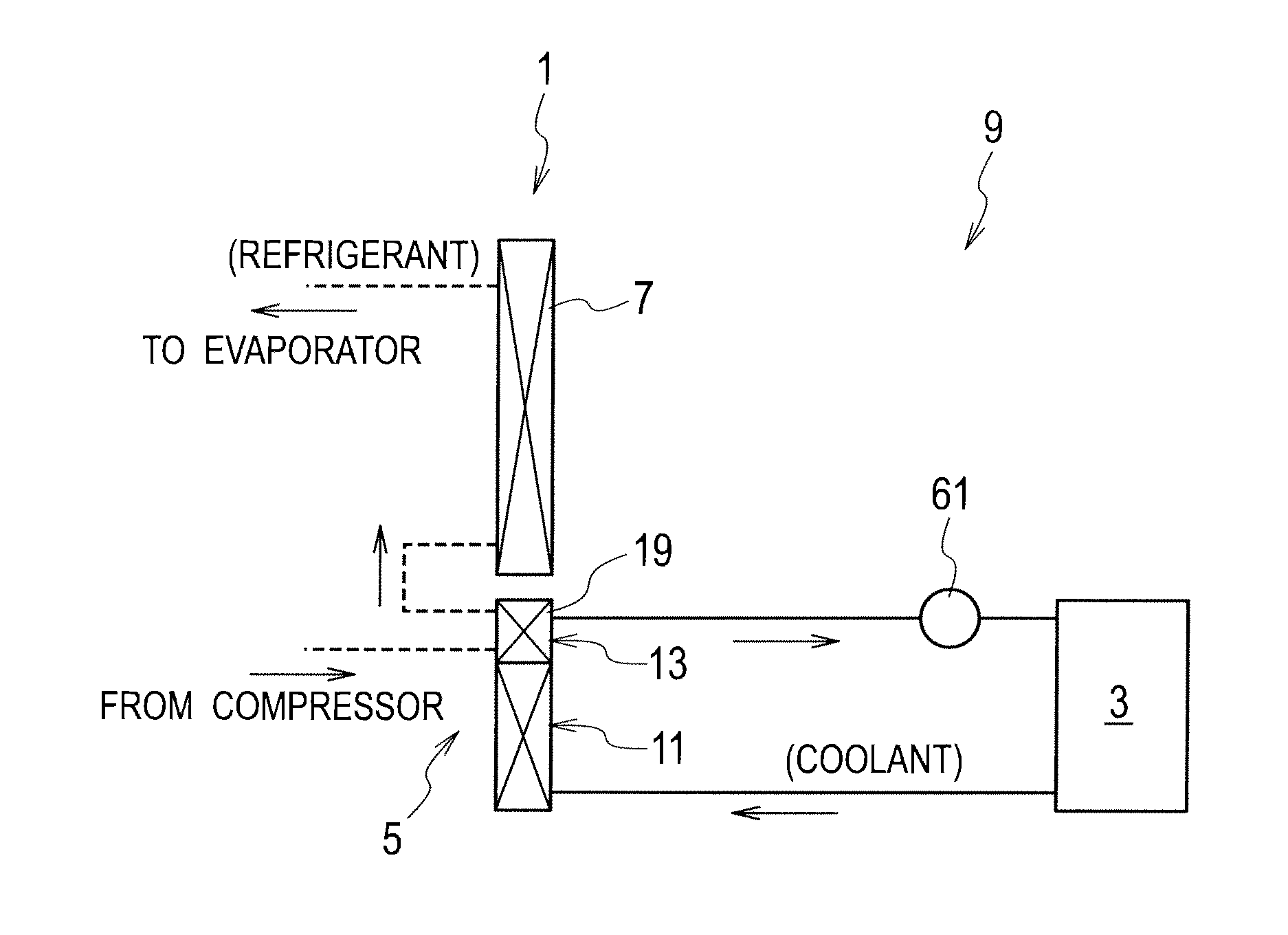
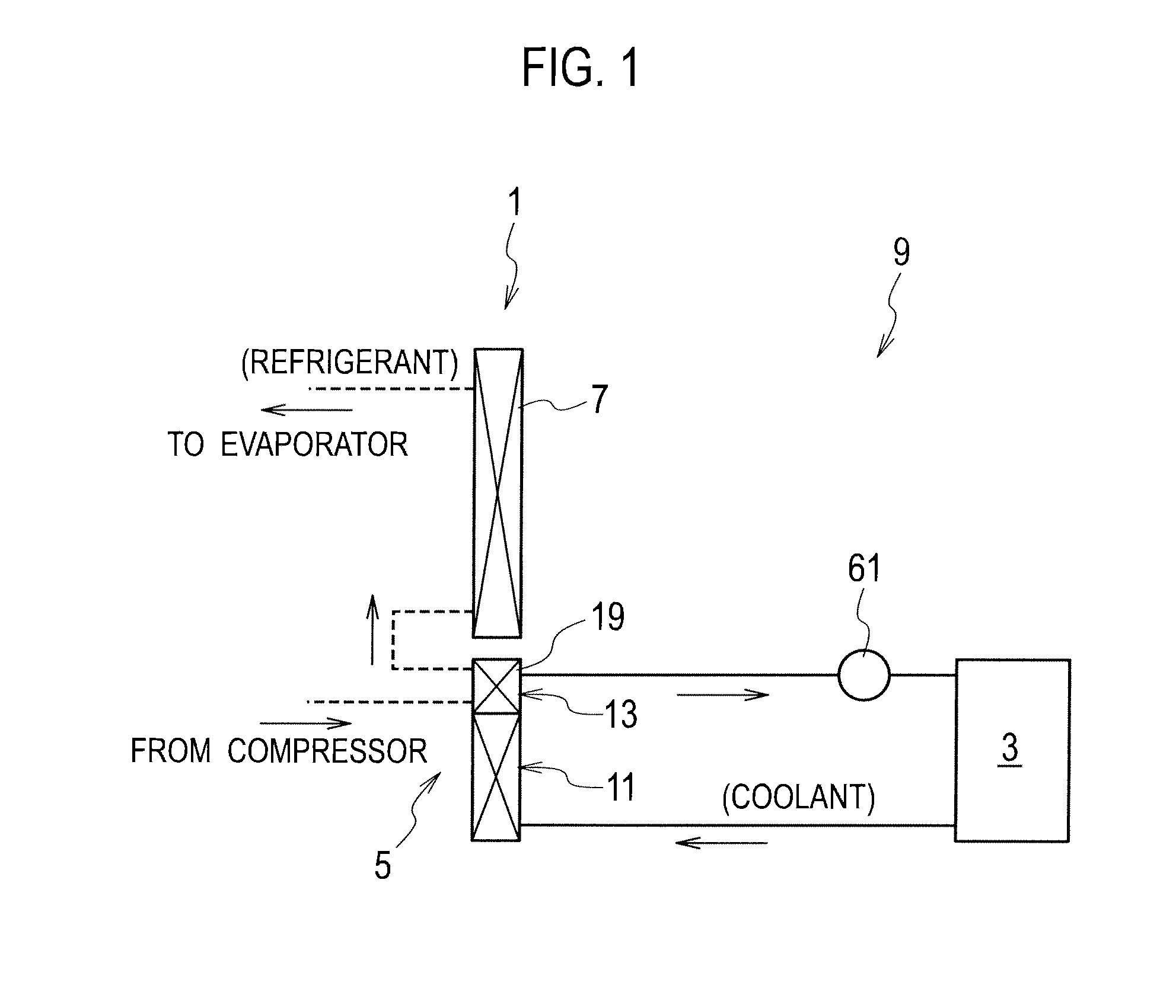
[0033]A combined heat exchanger 1 according to a first embodiment will be explained with reference to FIGS. 1 to 7. As shown in FIG. 1, the combined heat exchanger 1 is used in a cooling system 9 in a hybrid electric vehicle that has an engine (internal combustion engine: not shown) and an electric motor 3 as sources of a driving force.

[0034]The combined heat exchanger 1 is used in the cooling system 9 that includes a sub-radiator 5 (first air-cooled heat exchanger) and a condenser 7 (second air-cooled heat exchanger) as shown in FIG. 1. The sub-radiator 5 cools coolant for the drive motor 3 and control devices (heat generators other than the engine) such as an inverter or a converter. On the other hand, the condenser 7 cools air-conditioning refrigerant.

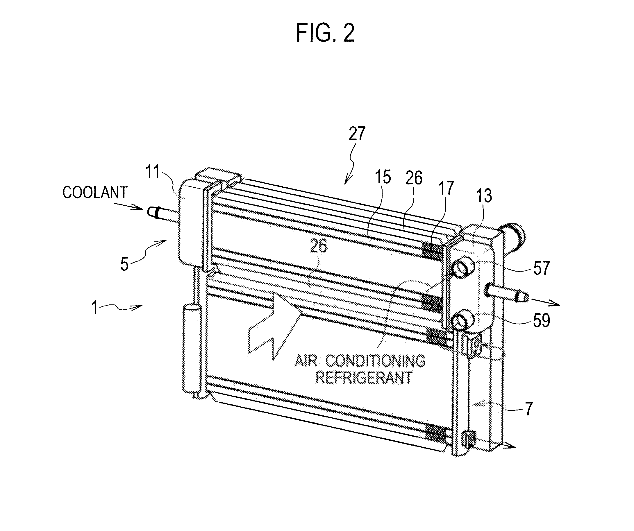
[0035]The sub-radiator 5 includes an upstream tank 11, a downstream tank 13, flat tubes 15 (flow channel members), heat release fins 17, and a water-cooled heat exchanger 19 as shown in FIGS. 1 to 3. The coolant flows into the upstr...

second embodiment

[0052]A combined heat exchanger according to a second embodiment will be explained with reference to FIGS. 8(a) and 8(b).

[0053]In the combined heat exchanger according to the present embodiment, an inner fin (refrigerant-passage unit) 101 fixed within the shell tube (refrigerant-passage unit) 21 is extended to circularly curved portions located at its both ends in the flow direction of the refrigerant. In addition, a pair of slits 103 extended from the inflow hole 51 is formed on both sides of the inflow hole 51. Similarly, a pair of slits 105 extended from the outflow hole 53 is formed on both sides of the outflow hole 53. The inner fin 101 is brazed with the shell tube 21 at its top edges of the corrugated shape and at its both ends in the flow direction. Therefore, anti-pressure strength of tube is ensured to its both ends in the flow direction.

[0054]The slits 103 and 105 are disposed to extend over some of the grooves 55. The refrigerant is spread (from the inflow hole 51: the s...

third embodiment

[0057]A combined heat exchanger according to a third embodiment will be explained with reference to FIGS. 9(a) and 9(b).

[0058]In the combined heat exchanger according to the present embodiment, notches 153 and 155 are formed on the inner fin (refrigerant-passage unit) 151. The upper notch 153 is provided in the width direction along the end 157 (FIG. 4) of the shell tube 21 on a side of the inflow ports 43 and 45. Similarly, the lower notch 155 is provided in the width direction along the end 159 (FIG. 4) of the shell tube 21 on a side of the outflow ports 47 and 49.

[0059]In the combined heat exchanger according to the present embodiment, the notches 153 and 155 are disposed to extend all of the grooves 55. The refrigerant is spread (from the inflow hole 51: the notch 153) in an almost perpendicular direction (in the width direction) to its flow direction due to the notches 153 and 155, and then collected (to the notch 155: the outflow hole 53). Since the refrigerant flows in a full...


PUM


Abstract

A combined heat-exchanger includes a first air-cooled heat-exchanger for cooling coolant for a heat generator other than an internal combustion engine in an automobile and a second air-cooled heat-exchanger for cooling refrigerant for air-conditioning. The first air-cooled heat-exchanger includes an upstream tank into which the coolant flows, a downstream tank form which the refrigerant flows out, flow channel members that communicate the upstream tank with the downstream tank, heat release fins that are alternately stacked with the flow channel members, and a water-cooled heat-exchanger for cooling the refrigerant. The water-cooled heat-exchanger is disposed within the downstream tank, and includes an inlet port to which the refrigerant flows at its upper portion and an outlet port from which the refrigerant flows out at its lower portion. According to the heat-exchanger, staying of oil mixed in the refrigerant can be prevented, heat exchange efficiency can improve and downsizing can be achieved.

Description

TECHNICAL FIELD[0001]The present invention relates to a combined heat exchanger that uses plural types of refrigerants (e.g. engine coolant and air-conditioning refrigerant) in a cooling cycle for an automobile.BACKGROUND ART[0002]A heat exchanger is disclosed in Japanese Patent Application Laid-Open No. 2006-162176 [Patent Document 1].[0003]This heat exchanger is used in an air conditioner for a vehicle, and a heat exchanger for air-conditioning refrigerant is implemented in a tank (header) of an air-cooled heat exchanger for engine coolant to cool air-conditioning refrigerant by air-cooled coolant. In this heat exchanger for air-conditioning refrigerant, the refrigerant is flown into from its lower side and frown out from its upper side.[0004]Oil for a compressor is subject to be mixed in air-conditioning refrigerant, and the refrigerant circulates in a system together with the mixed oil. Some of the mixed oil separates from the refrigerant.SUMMARY OF INVENTION[0005]In the heat ex...

Claims


Application Information

Patent Timeline
Patent Type & Authority Applications(United States)
IPC IPC(8): F28D15/00
CPCF28F9/0234F28D1/0452
Inventor IWASAKI, MITSURUMEGURIYA, YUICHI
Owner CALSONIC KANSEI CORP
Why Eureka
Try Eureka