Eureka AIR delivers breakthrough ideas for toughest innovation challenges, trusted by R&D personnel around the world.

Device in valve

A valve and valve housing technology, applied in the field of devices in valves, can solve the problems of complex and expensive device manufacturing, and achieve the effects of low pressure gradient, reduced risk of vibration, and high stability

Inactive Publication Date: 2004-08-04
NAF
View PDF0 Cites 0 Cited by
  • Summary
  • Abstract
  • Description
  • Claims
  • Application Information

AI Technical Summary

Problems solved by technology

However, the devices are relatively complex to manufacture and thus expensive

Method used


Image

  • Device in valve
  • Device in valve
  • Device in valve

Examples


Embodiment Construction

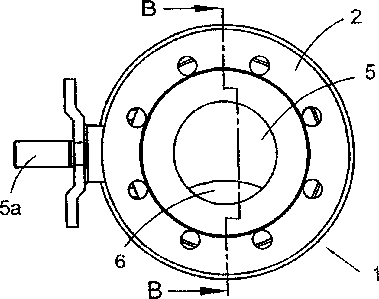
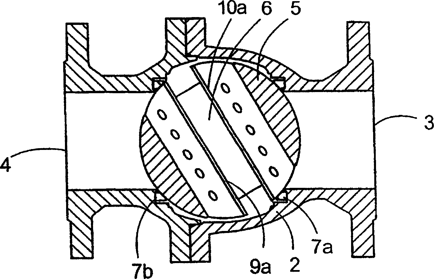
[0013] The spherical valve 1 comprises a valve housing 2 on opposite sides of which an inlet 3 and an outlet 4 are arranged. A valve body 5 with a substantially cylindrical passage 6 is pivotally mounted inside the valve housing 2 . Figure 1a A shaft 5a connected to the valve body 5 for operating the valve body 5 is shown. In the fully open position of the valve 1, the inlet 3 and outlet 4 and the channels are in line with each other. Figure 1b Also shown are two annular seals 7a, 7b for sealing between the inlet 3 and outlet 4 and the valve body 5 respectively. Those skilled in the art will appreciate that in some applications only one seal is required.

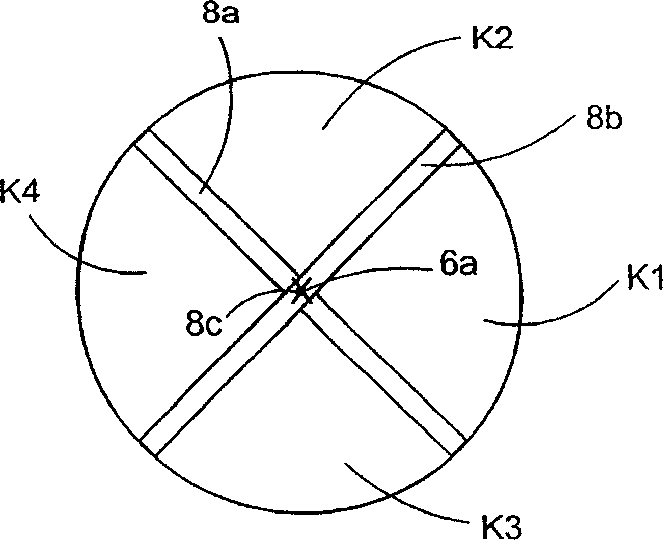
[0014] According to the invention, at least one pair of intersecting walls 8a, 8b (see Figure 2a ) and 9a, 9b and 10a, 10b (see FIG. 3a) are set in the channel 6. as from Figure 2a and 4 As seen, we will now first refer to the Figure 2a , 2b and 4 detail the construction of a pair of walls arranged like a cross i...


PUM


Abstract

A valve (1) has a valve housing (2) with an inlet (3) and outlet (4), a valve body (5), provided with an essentially cylindrical passage (6) and pivotally mounted in the housing (2). Essentially plane walls, defining chambers between them and provided with through openings (11; 11') are arranged in the passage (6). Upon opening the valve the inlet connects solely with one chamber, which via wall openings and intermediate chambers connects with the chamber opposite and the latter with the outlet. During the successive opening sequence of the valve more and more chambers and finally all chambers are made to connect with the inlet and the outlet respectively. The device has at least one pair of intersecting walls (8a, 8b; 9a, 9b, 10a, 10b). These are located in the passage (6), so that two opposing chambers (K1, K4; k1, k9) situated nearest to the inlet (3) and the outlet (4) respectively lie symmetrically in relation to a center plane, in which the central axis (6a) of the passage is situated during the rotational movement vice-versa (5) between the opened and the closed position and vice-versa.

Description

technical field [0001] The invention relates to a device in a valve, in particular of the type comprising a valve housing, on opposite sides of the valve housing an inlet and an outlet are arranged, preferably directly opposite each other, in the valve housing between the inlet and the outlet Between them, a valve body is provided, which has a roughly cylindrical channel and is pivotally mounted on the inner side of the valve housing, so that when the valve is in a fully open position, the channel and the inlet and outlet are located on a straight line with each other, determining the distance between the two. The chamber and the substantially planar wall provided with the through hole are arranged in the channel, at the beginning of the valve opening movement, the inlet is only connected to one chamber, and the chamber is connected to the opposite chamber via the wall opening, the intermediate chamber and the opposite chamber Connection, the latter is connected with the outle...

Claims


Application Information

Patent Timeline
Patent Type & Authority Patents(China)
IPC IPC(8): F16K5/06F16K47/04
CPCF16K47/045F16K5/0605Y10T137/86743
Inventor 珀·伦德奎斯特
Owner NAF
Why Eureka
Eureka Blog
Learn More