Rotary throttle valve for spark ignition type internal combustion engine
A spark ignition, internal combustion engine technology, applied in mechanical equipment, engine components, engine control, etc., can solve problems such as increasing flow resistance and pressure loss, and achieve the effect of reducing flow resistance and pressure loss
- Summary
- Abstract
- Description
- Claims
- Application Information
AI Technical Summary
Problems solved by technology
Method used
Image

Examples
Embodiment 1
[0034] Hereinafter, the embodiment of this invention application is demonstrated based on drawing.
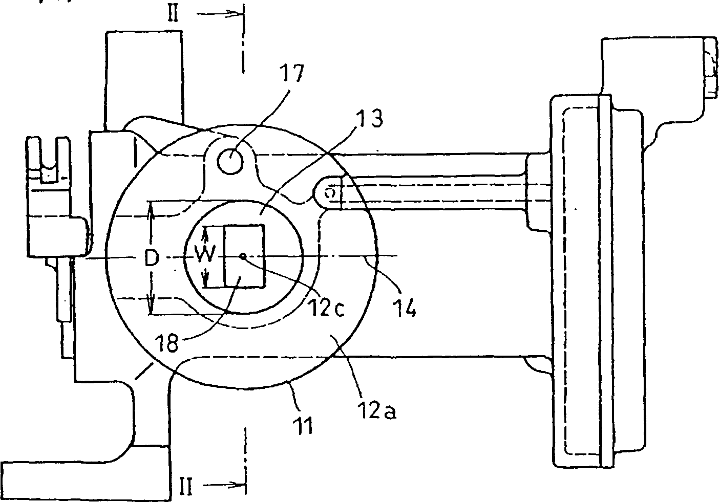
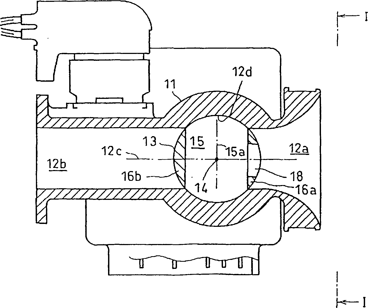
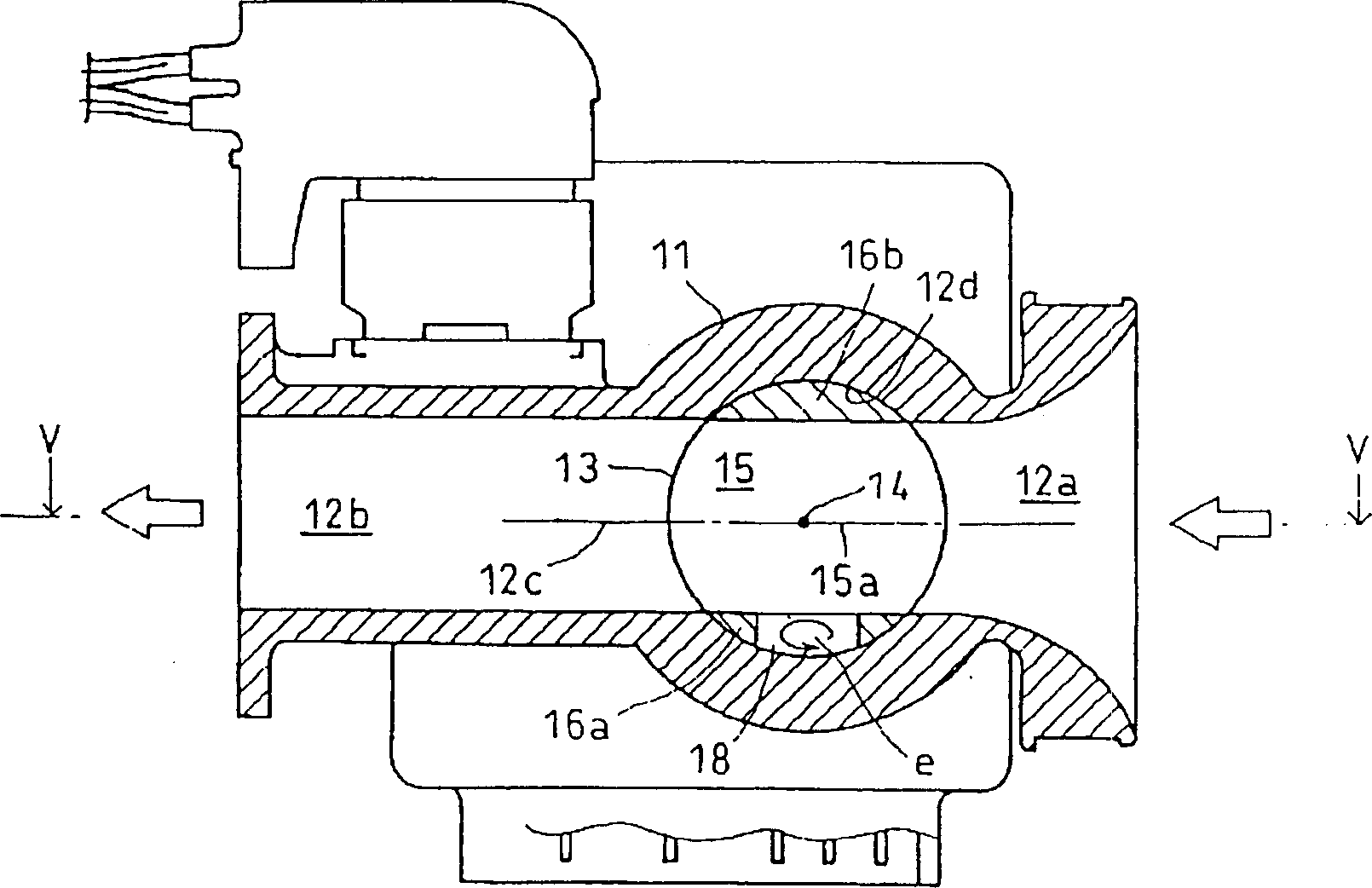
[0035] figure 1 It is a front view showing the closed state of the rotary throttle valve according to an embodiment of the present invention ( figure 2 The view in the direction of the I-I arrow), figure 2 yes figure 1 A cross-sectional view in the direction of the II-II arrow, image 3 is also a cross-sectional view showing the closed state, Figure 4 It is also a sectional view showing a half-open state, and Fig. 5 is image 3 Cross-sectional view in the direction of the V-V arrow.
[0036] In these figures, 11 is a valve casing, and suction passages 12a, 12b are formed in the valve casing. In the above-mentioned valve case 11, a cylindrical recess 12d having an axis line 24 intersecting the central axis 12c of the suction passages 12a, 12b is formed, and the cylindrical valve body 13 is rotatably embedded in the circle around the axis 14. inside the cylindrical re...
Embodiment 2
[0043] Subsequently, Figure 6 It is a front view (view in the VI-VI arrow direction of FIG. 7 ) that represents another embodiment of the application for the present invention in a closed state of a rotary throttle valve. FIG. 7 is Figure 6 The cross-sectional view in the direction of the arrow VII-VII, Figure 8 is also a cross-sectional view showing the fully open state, Figure 9 It is also a cross-sectional view showing a half-open state, Figure 10 It is a cross-sectional view in the X-X arrow direction of FIG. 8 .
[0044] In these figures, 21 is a valve casing, and suction passages 22a, 22b are formed in the valve casing. In the valve housing 21, a cylindrical recess 22d is formed with the axis 14 intersecting the central axis 22c of the suction passages 22a, 22b as the axis, and the cylindrical valve body 23 is rotatably embedded in the cylinder around the axis 24. inside the shaped recess. Furthermore, the valve body 23 is provided with a passage 25 communicating...
Embodiment 3
[0049] Subsequently, Figure 11 is a cross-sectional view showing a half-open state in another embodiment of the present invention. In this embodiment, like the first embodiment, the channel 35 of the valve body 33 points to the direction intersecting with the central axis 35a of the channel and runs through one 36a of the two opposite valve walls 36a, 36b to open a passage valve. The through hole 38 on the rotating outer surface of the body 33. Like the second embodiment, on the two positions of the inclined wall surface of the conical inflow passage 32a, a plane parallel to the central axis 32c and the valve rotation axis 34 including the upstream suction passage is opened and the depth does not exceed the valve. The grooves 39a, 39b of the valve wall 36a, 36b thickness of the body 33.
[0050] As a result, in the half-open state, all of the eddy currents a, b, and c are reduced, thereby reducing flow resistance.
[0051] Although the above-mentioned embodiments of the pr...
PUM
 Abstract
Description
Claims
Application Information
 - R&D
- Intellectual Property
- Life Sciences
- Materials
- Tech Scout
- Unparalleled Data Quality
- Higher Quality Content
- 60% Fewer Hallucinations
Browse by: Latest US Patents, China's latest patents, Technical Efficacy Thesaurus, Application Domain, Technology Topic, Popular Technical Reports.
© 2025 PatSnap. All rights reserved.Legal|Privacy policy|Modern Slavery Act Transparency Statement|Sitemap|About US| Contact US: help@patsnap.com