Supercharge Your Innovation With Domain-Expert AI Agents!

Electric vacuum cleaner

A technology for vacuum cleaners and dust, applied in the directions of vacuum cleaners, suction nozzles, suction hoses, etc., can solve problems such as increasing the burden

Inactive Publication Date: 2004-10-06
HITACHI LTD
View PDF3 Cites 4 Cited by
  • Summary
  • Abstract
  • Description
  • Claims
  • Application Information

AI Technical Summary

Problems solved by technology

[0008] Also, in the prior art in which the handle portion and the suction hose portion are rotatably provided, since the pipe shaft constituting the curved connection portion of the handle portion and the pipe shaft of the suction hose portion are rotatably directly connected Since it is connected, when the handle part is twisted left and right, the suction hose part will swing to the left and right with the grip part as the center, and as a result, the burden on the wrist will increase.

Method used


Image

  • Electric vacuum cleaner
  • Electric vacuum cleaner
  • Electric vacuum cleaner

Examples


Embodiment Construction

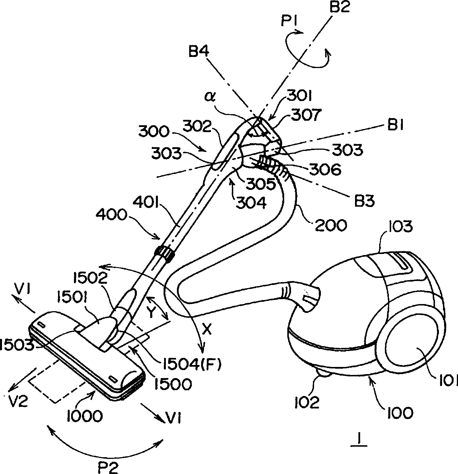
[0056] Below, refer to Figure 1 to Figure 4 0 Each embodiment of the electric vacuum cleaner of the present invention will be described.

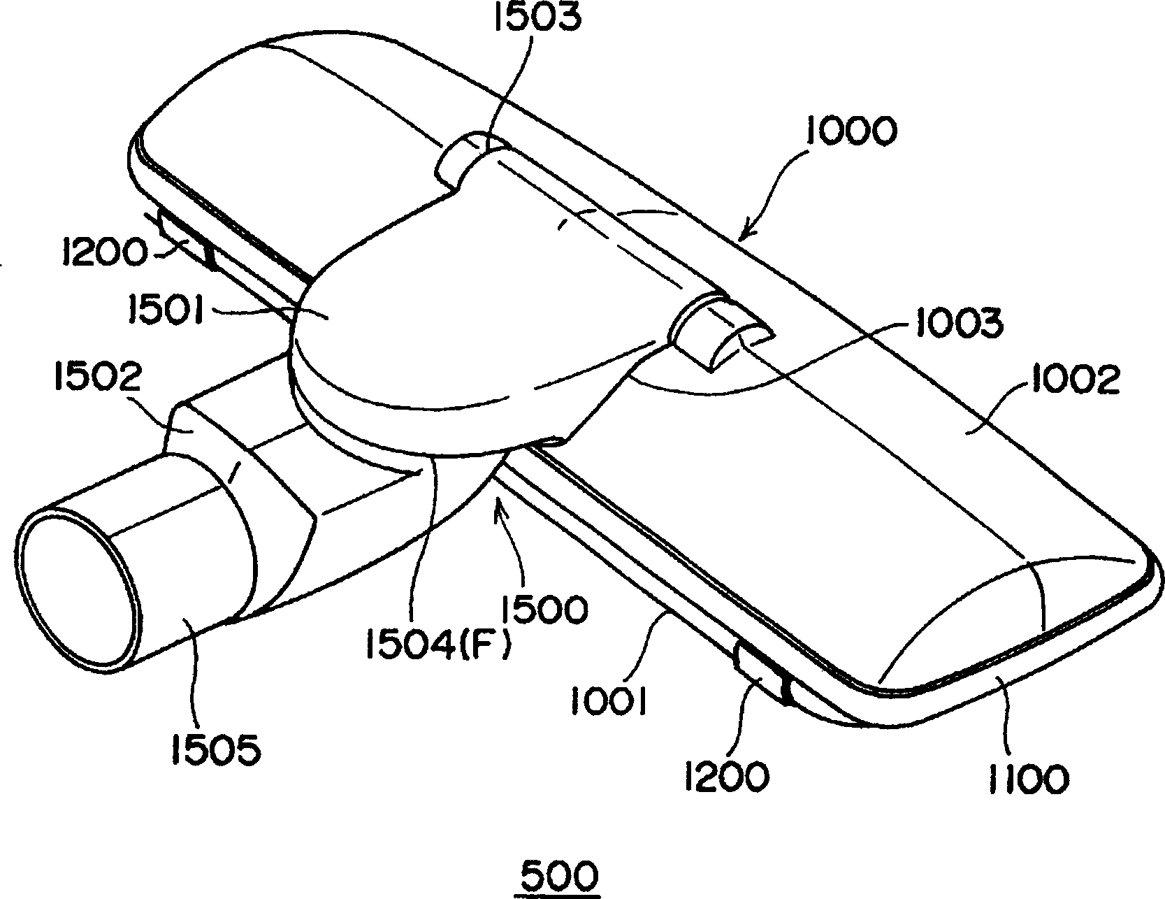
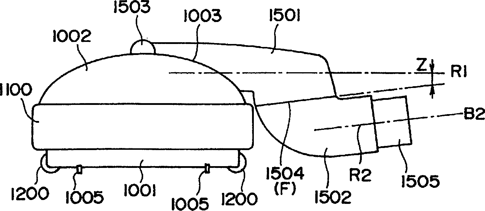
[0057] Figure 1 to Figure 1 7 is the first embodiment of the electric vacuum cleaner of the present invention, wherein, figure 1 is a three-dimensional view of the appearance of the electric vacuum cleaner, Figure 2 to Figure 6 This is an external view of the suction port, Figure 7 and Figure 8 is a sectional view of the suction port, Figure 9 Figure 10 is an explanatory diagram of the operation of the suction port, Figure 11 to Figure 1 6 is an explanatory diagram of the handle, and FIG. 17 is a diagram of the use state of the suction port.

[0058] First, refer to figure 1 A first embodiment of the electric vacuum cleaner of the present invention will be described. Included by symbol 1 is an electric vacuum cleaner, which consists of: an electric vacuum cleaner body 100 with a mechanism not shown in the figure for sucking d...


PUM


Abstract

A electric vacuum cleaner, comprises: a joint pipe, the sucking port main body is communicated to the connecting pipe when the sucking port main body is connected to the connecting pipethe sucking port main body; the joint pipe member comprises a first joint pipe rotatably connected to the suction port main body at one end and a second joint pipe rotatably connected to the other end of the first joint pipe at one end; a descending pipe part at the other end of the first joint pipe and an ascending pipe part at the one end of the second joint pipe are rotatably coupled together; and handle shank member.

Description

technical field [0001] The invention relates to an electric duster. Background technique [0002] The suction port used on the existing electric vacuum cleaner is connected to the handle part through the extension pipe, and by making the handle part rotate around the axis of the longitudinal direction of the extension pipe, the It has a curved tubular shape on the connection structure, and can be rotated to a certain extent. These structures are disclosed, for example, in Japanese Patent Laid-Open Publication No. Hei 5-245073. [0003] In addition, in recent years, through the improvement of the suction port, the twist angle of the handle part is related to the rotation angle of the suction port, and an electric vacuum cleaner that can rotate the rotation angle of the suction port up to 180 degrees. Implemented by Hitachi, Ltd. in 1997. [0004] Also, for example, in the "Japanese Patent Laid-Open No. 4-161126" publication of the Japanese Patent Laid-Open Gazette, it is s...

Claims


Application Information

Patent Timeline
Patent Type & Authority Patents(China)
IPC IPC(8): A47L9/02A47L9/04A47L9/24
CPCA47L5/362A47L9/248
Inventor 漆原笃彦铃木成彦山口笃志织田胜星野毅砂川正郎
Owner HITACHI LTD
Features
  • R&D
  • Intellectual Property
  • Life Sciences
  • Materials
  • Tech Scout
  • Unparalleled Data Quality
  • Higher Quality Content
  • 60% Fewer Hallucinations
Learn More