

Electric tool with interchangeable tool post
A technology of electric tools and tool holders, which is applied in the field of electric tools and can solve the problems of changing the drilling speed and energy consumption
- Summary
- Abstract
- Description
- Claims
- Application Information
AI Technical Summary
Problems solved by technology
Method used
Image

Examples
Embodiment Construction
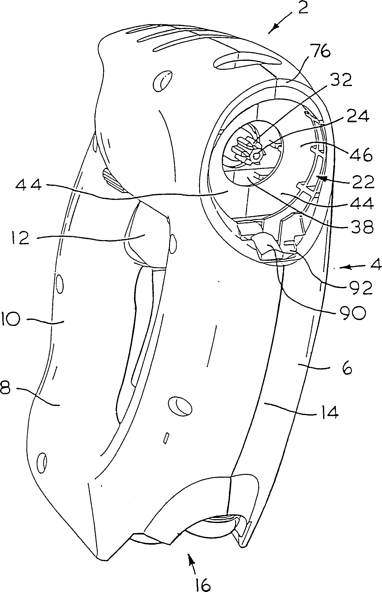
[0020] see figure 1 , generally indicated by the reference numeral (2), includes a body portion (4) conventionally formed from two clamshell halves (6, 8). The two clamshell halves fit together to enclose the internals of the power tool as described below.
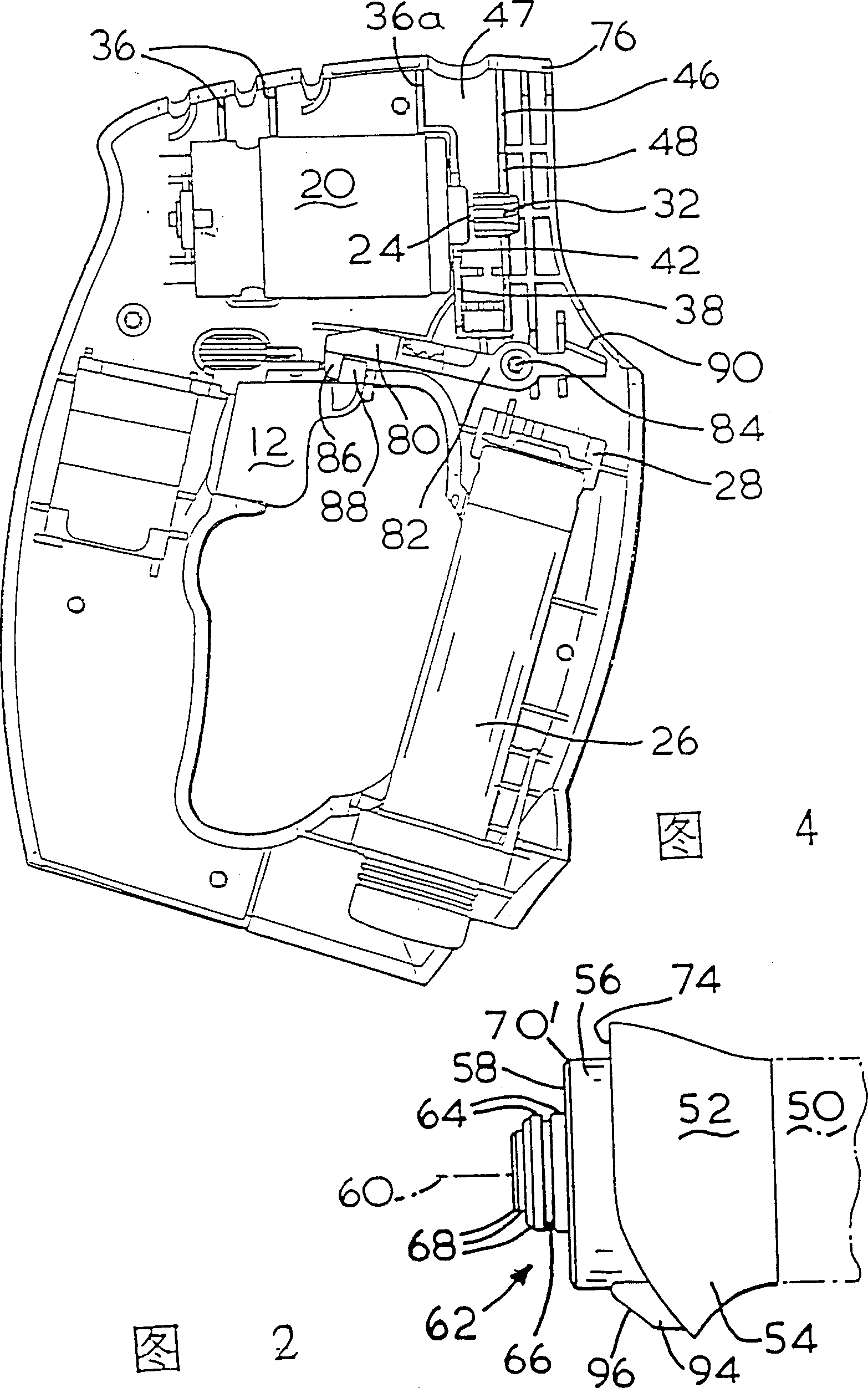
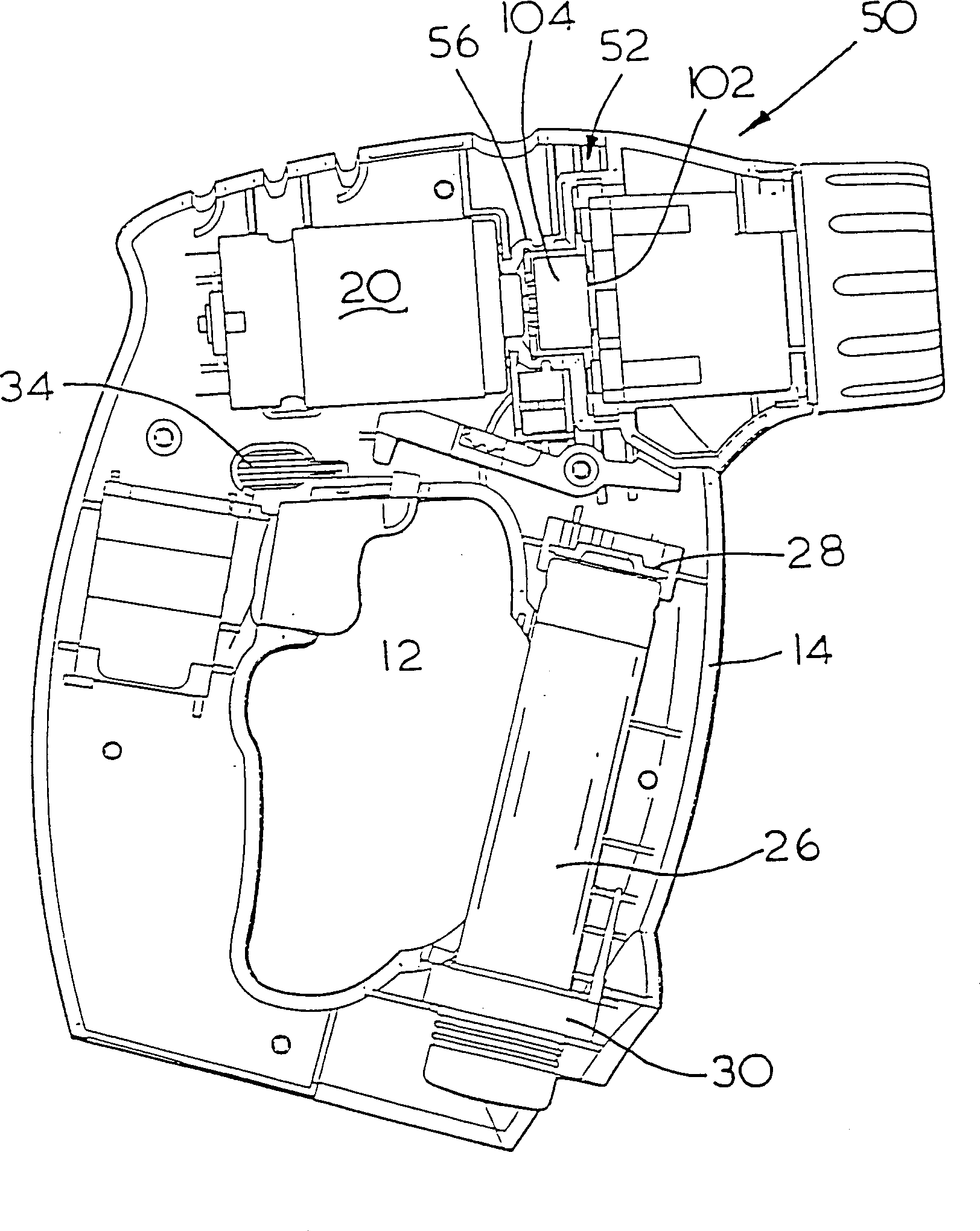
[0021] The main body portion (4) defines a generally D-shaped body and the rear portion (10) of the body defines a conventional pistol grip gripped by the user. Projecting inwardly from the rear portion (10) is an actuation trigger (12) which can be operated by the user's index finger in the normal manner of operation of the power tool mechanism. This pistol grip structure is a conventional structure, so the part related to this embodiment will not be further described. The front portion (14) of the D-shaped body can be used for dual purposes, it can provide protection when the user's hand grasps the pistol grip portion (10), and can also be used to accommodate two batteries (26) (see Figure 5 ) to provide power to too...
PUM
 Abstract
Description
Claims
Application Information