Rotary servovalve and control system

a rotary servo valve and control system technology, applied in the direction of valve operating means/release devices, mechanical equipment, transportation and packaging, etc., can solve the problems of high manufacturing tolerance, high cost of the servo valve system, and lack of the requisite torque for commercial use in many applications, and the prior rotary servo valve and control system lacks the torque requisite to achieve the effect of commercial utility in many applications

Inactive Publication Date: 2001-08-07
WOODWORTH RAYMOND DEXTER
View PDF26 Cites 44 Cited by
  • Summary
  • Abstract
  • Description
  • Claims
  • Application Information

AI Technical Summary

Problems solved by technology

Such servovalve systems are expensive and require high manufacturing tolerances.
They are also sensitive to contamination and clogging.
Furthermore, they typically require continuous flow from a pump in order to operate.
In the event of a power failure a rather intricate arrangement of mechanical elements, including torque rods and springs, is required to center the servo valve in order to halt fluid flow.
Prior rotary servovalve and control systems lack the r...

Method used


Image

  • Rotary servovalve and control system
  • Rotary servovalve and control system
  • Rotary servovalve and control system

Examples


Embodiment Construction

FIGS. 10 and 11 provide an overview of a rotary servovalve system according to the invention. This system includes a mechanical section 50, illustrated generally in FIG. 10, and an electrical control circuit 52, illustrated in block diagram form in FIG. 11.

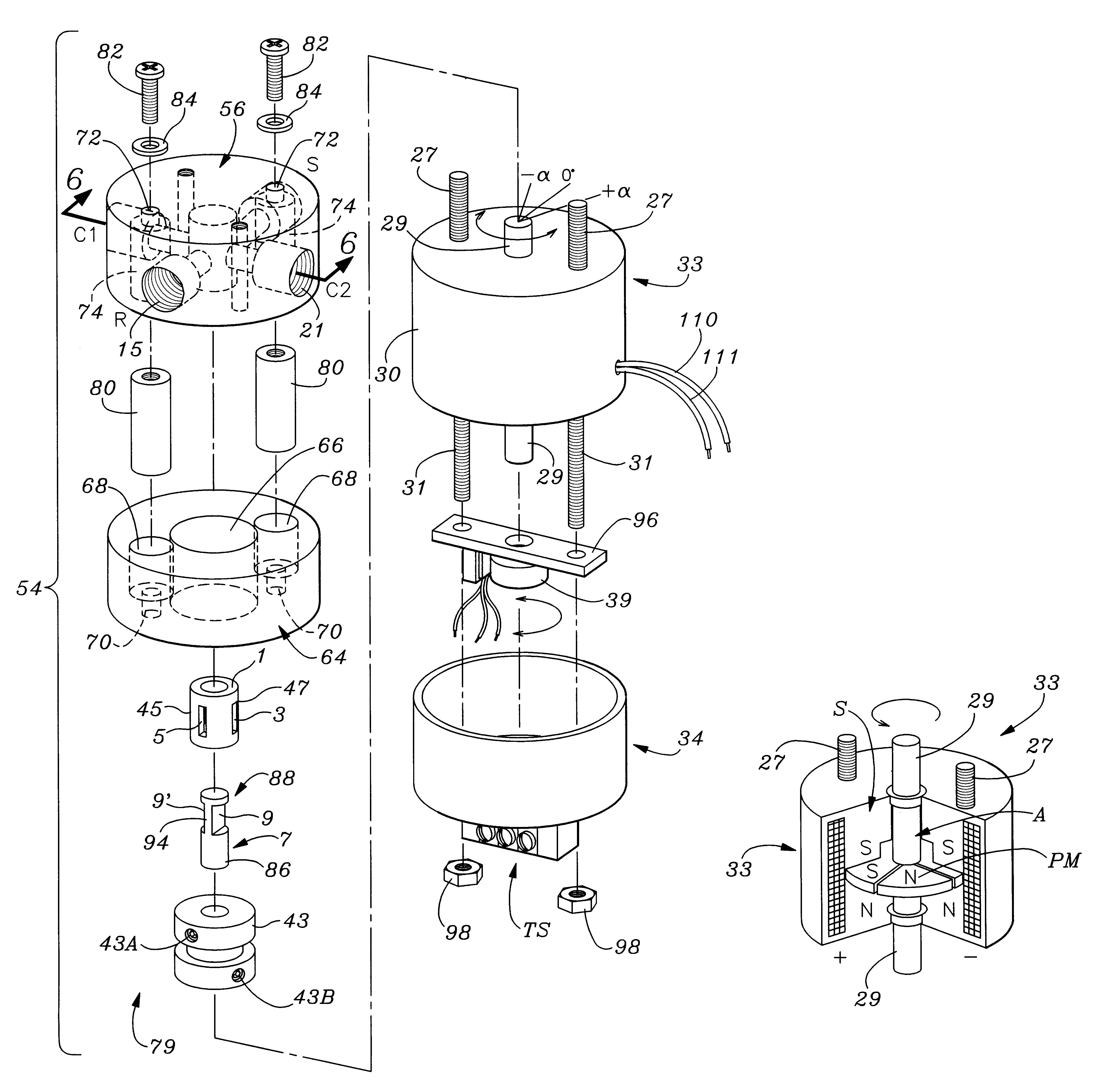
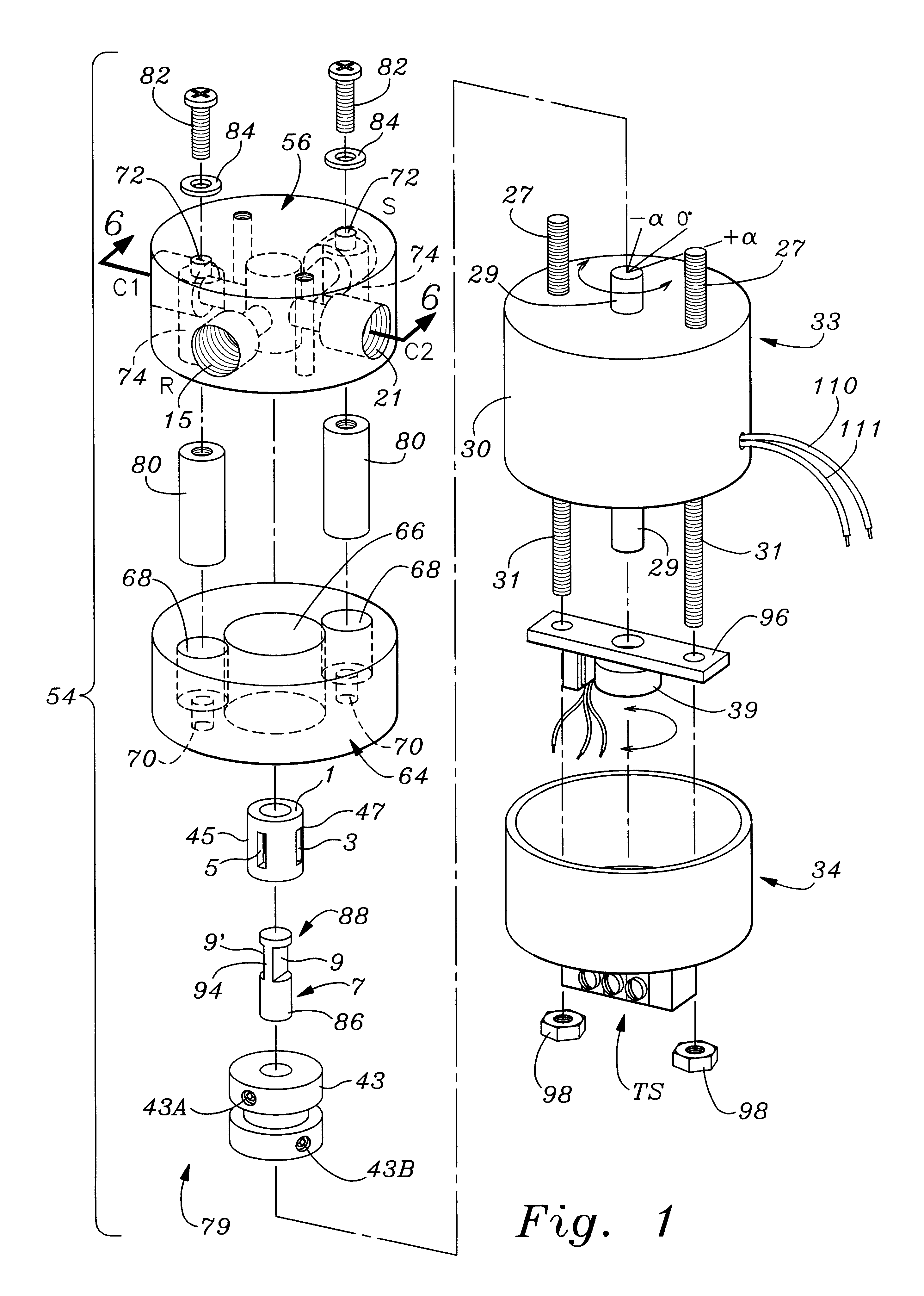
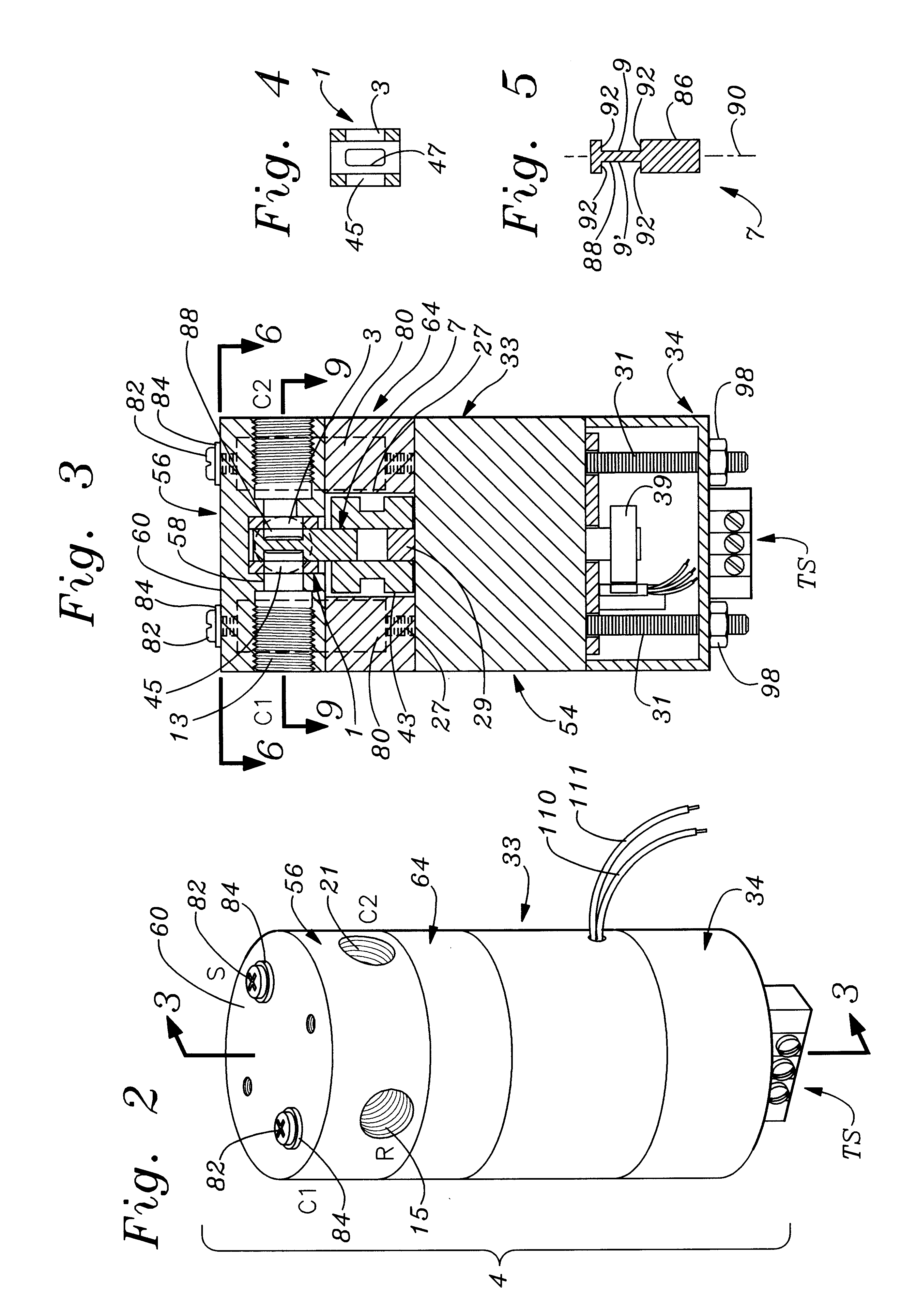
The mechanical section 50 of the rotary servovalve system of the invention has a valve and solenoid assembly 54 operated through signals from the control circuit 52 that are connected by appropriate wires to a terminal strip TS, illustrated in FIGS. 1-3. The rotary servovalve and solenoid assembly 54 includes an Ultramag.RTM. rotary actuator 33 that is seated in a hollow, cup-shaped end cap 34. The end cap 34 has a cylindrical, annular wall open at its upper end to receive the rotary magnetic solenoid 33 and is closed at its lower end. The terminal strip TS is located externally on the lower, closed end of the hollow cap 34.

The rotary magnetic solenoid actuator 33 is of the type that includes an armature with at least one permanen...


PUM


Abstract

An improved rotary servovalve system employs a rotary magnetic solenoid having an armature that includes at least one permanent magnet. The armature is rotatable relative to a stator formed as an electromagnet which is energizable to create alternative electromagnetic fields having opposite polarities from each other. When deenergized, the stator allows the armature to return to a neutral, null position from positions of extreme rotation in opposite angular directions due to the magnetic force of the permanent magnet of the armature. The armature is coupled to carry a movable valve element in angular rotation therewith, so that flow through the servovalve of the system can occur in alternative directions. Also, the valve element is biased toward a position in which all of the valve ports are closed when power is removed from the rotary solenoid. The control circuit employed in the rotary servovalve system expands the bandwidth of response of the solenoid actuator by compensating for frequency variations in the input command signal and in the feedback signal. This compensation is achieved utilizing a combined proportional, integral, and differential amplification circuit. Also, imbalance of fluid forces within the servovalve mechanism can be avoided by utilizing a pair of inlet orifices, a pair of outlet orifices, a pair of first fluid control orifices, and a pair of second fluid control orifices. The orifices within each pair are located on opposite sides of the valve housing from each other.

Description

1. Field of the InventionThe present invention relates to servovalves that are used to transfer quantities of fluid. The rotary servovalve and control system of the invention is particularly useful in situations requiring rapid response and precision control of fluid flow.2. Description of the Prior ArtMany different mechanical and electrical servovalve systems have been employed for controlling fluid flow in industrial and manufacturing environments, as well as in other applications. Fluid servovalve control systems which require precise and highly responsive control are employed in a multitude of widely varying applications, including the control of robots, the operations of presses for manufacturing rubber and plastic parts, the control of tensioning devices in the paper industry, automotive vehicle and parts manufacturing, petroleum refining operations, and numerous other applications.In many of the applications in which servo control valve systems are utilized, pressurized flui...

Claims


Application Information

Patent Timeline
IPC IPC(8): F15B13/04F15B13/00F16K31/04F16K11/085F16K11/02
CPCF15B13/0406F16K31/042F16K11/085F15B2013/0409Y10T137/86646
Inventor WOODWORTH, RAYMOND DEXTERBOBROW, JAMES EDWIN
Owner WOODWORTH RAYMOND DEXTER
Why Eureka
Try Eureka