Mechanical keypad with touch pad function

a technology of touch pad and mechanical keypad, which is applied in the direction of instruments, coding, pulse techniques, etc., can solve the problems of insufficient input of non-pre-determined signals by mechanical keypad, insufficient use of touch pad for inputting pre-determined signals, and insufficient fabrication cost of touch pad, so as to achieve maximum convenience and utility

Inactive Publication Date: 2010-12-09
ICHIA TECH
View PDF16 Cites 46 Cited by
  • Summary
  • Abstract
  • Description
  • Claims
  • Application Information

AI Technical Summary

Benefits of technology

[0009]The inventors of the present invention propose an invention which is reasonably designed and able to solve the aforesaid problems. The input device of the present invention possesses both of the convenience of the mechanical keypad and the advantages of the touch pad. When applied in an electronic device, a mobile electronic device in particular, the input device of the present invention may provide the users with maximal convenience and utility.

Problems solved by technology

Although a mechanical keypad is good at inputting certain pre-determined signals quickly, such as for chatting or for drafting documents, and is very popular for this purpose, the mechanical keypad is however too weak to input these non-pre-determined signals because each key of the mechanical keypad can only represent one or a few pre-determined signals once the mechanical keypad is used for inputting non-pre-determined signals, such as for driving a cursor in a graphic-oriented system or for constructing abstract patterns, Chinese characters for example.
Nevertheless, the touch pad is less useful for inputting pre-determined signals.
On the other hand, the fabricating cost of the touch pad is too high but the life is too short.
However, the prior art does not disclose that the keycaps may be mutually connected.
In addition, the prior art also lacks a backlight source as well as a light guide film (LGF) for the uniform distribution of light.
As a result, this design is not good for all purposes.

Method used


Image

  • Mechanical keypad with touch pad function
  • Mechanical keypad with touch pad function
  • Mechanical keypad with touch pad function

Examples


first embodiment

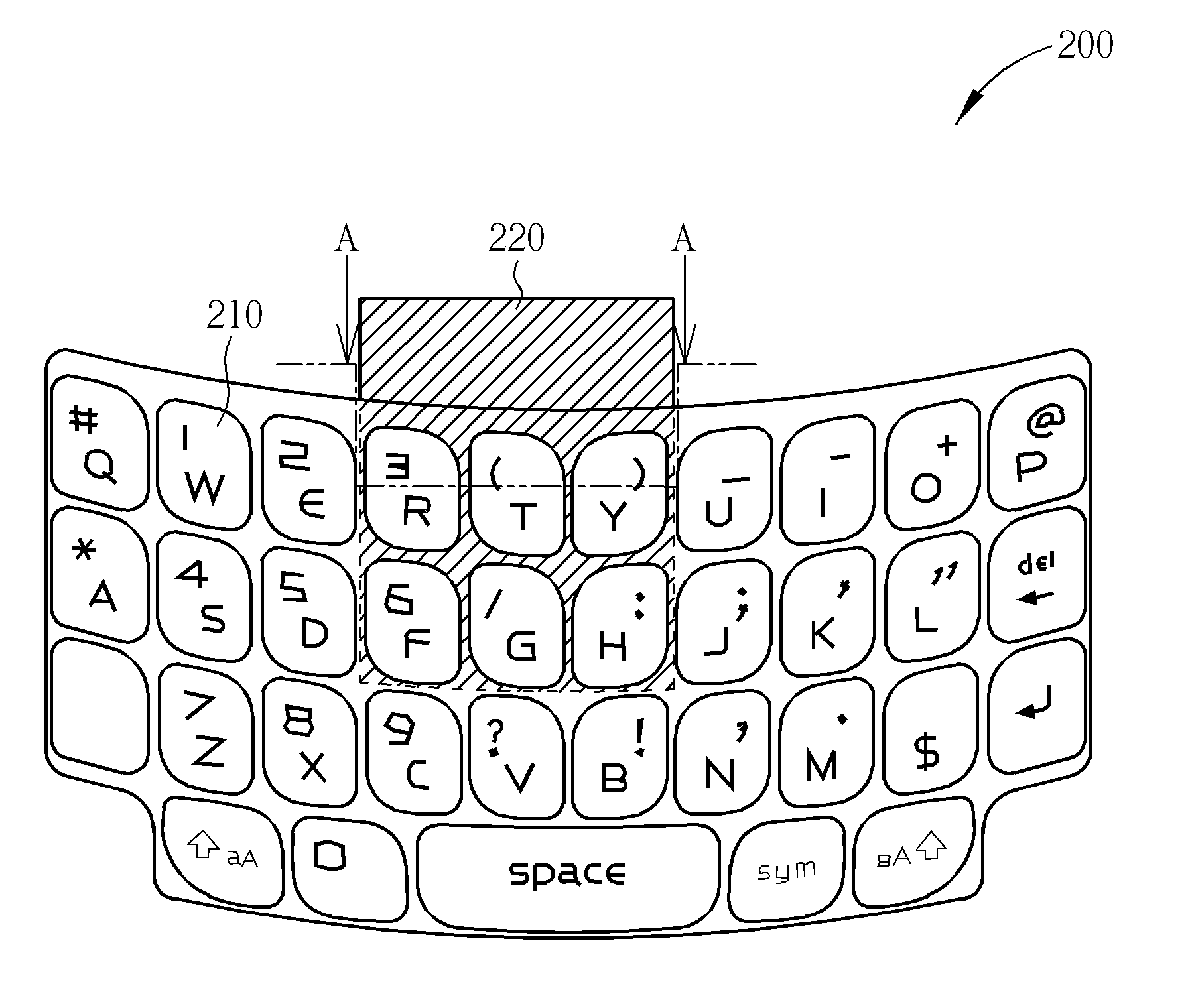
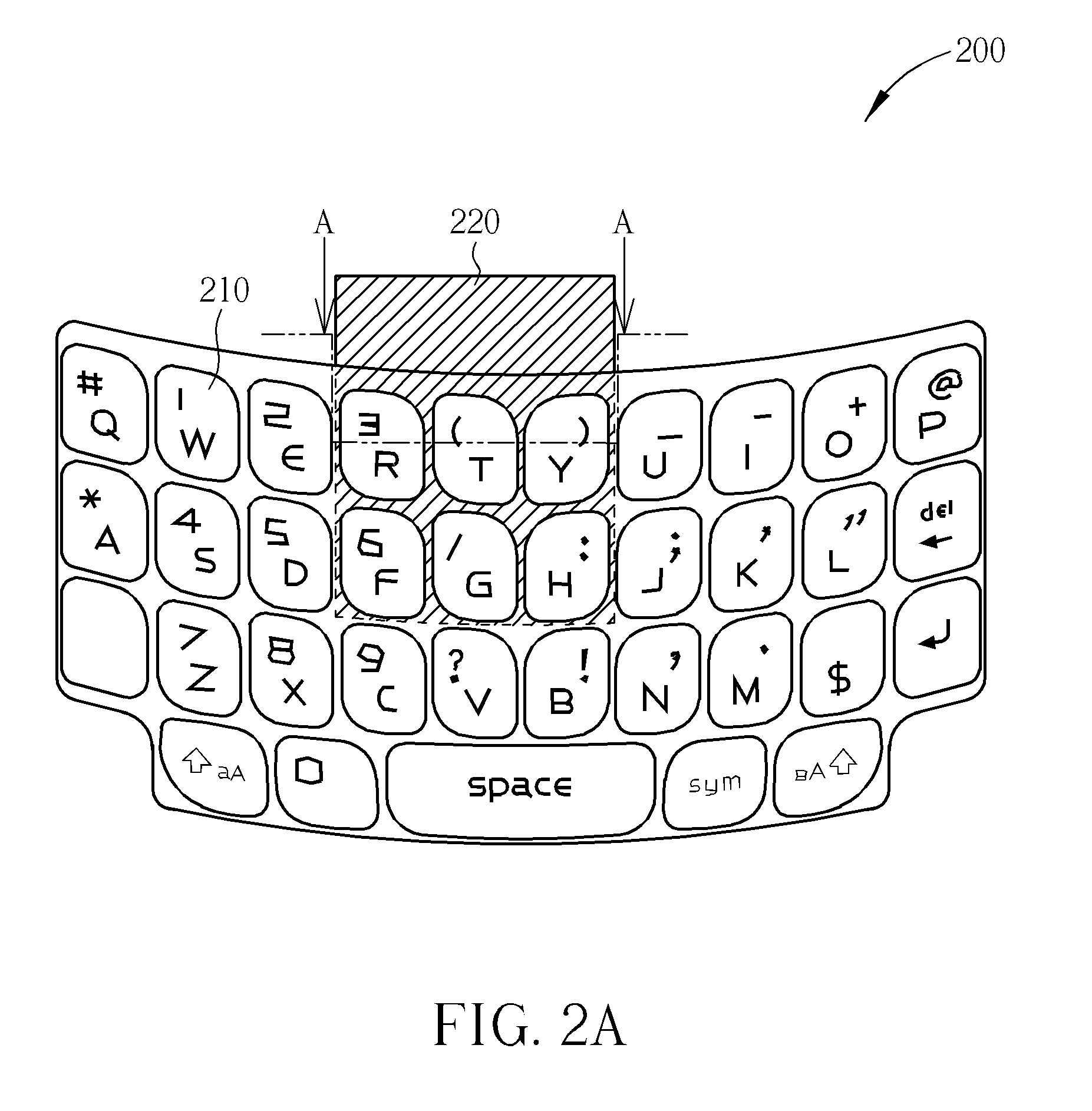
[0023]In one aspect of the present invention, a mechanical keypad 200 with touch panel function is provided. Please refer to FIG. 2A, illustrating a top view of the mechanical keypad with touch panel function of the present invention. FIG. 2B illustrates a sectional view along line A-A′ in FIG. 2A. The mechanical keypad 200 with touch panel function of the present invention includes a key set 210, a capacitive touch unit 220, an elastic layer 230, a backlight layer 240 and a circuit board 250. The key set 210 includes a plurality of keycaps 211, mutually independent for example, and a keytop 212 which entirely covers the keycaps 211. The keycaps 211 are usually made of polymers, such as plastics or silicone. For example, the keycaps 211 may have a section view of T shape.

[0024]The keytop 212 may be shaped by heating and molding, and the keycaps 211 may be shaped by plastic injection. In addition, the keytop 212 entirely covers all of the keycaps 211. The keytop 212 may be made of ma...

second embodiment

[0033]In a second aspect of the present invention, another mechanical keypad 300 with touch panel function is provided. Please refer to FIG. 3, illustrating a top view of the mechanical keypad with touch panel function of the present invention. FIG. 4 illustrates a cross-sectional view along line B-B in FIG. 3. Please refer to FIG. 4, the mechanical keypad 300 with touch panel function of the present invention includes a key set 310, a backlight layer 320, a capacitive touch unit 330, an elastic layer 340, and a circuit board 350. The key set 310 includes a plurality of mutually connecting keycaps 311 and a keytop 312 which entirely covers the mutually connecting keycaps 311. The mutually connecting keycaps 311 are usually made of polymers, such as a UV-curable resin. Each keycap 311 may be divided by a shallow trench 313. The keytop 312 entirely covers all of the keycaps 311. The keytop 312 may be made of materials such as PC or PET. The keytop 312 disposed on each one of the keyca...

third embodiment

[0039]In a third aspect of the present invention, still another mechanical keypad 400 with touch panel function is provided. Please refer to FIG. 5, illustrating a top view of the mechanical keypad with touch panel function of the present invention. FIG. 6 illustrates a cross-sectional view along line C-C in FIG. 5. Please refer to FIG. 6, the mechanical keypad 400 with touch panel function of the present invention, a film-in-plastic (FIP) keypad for example, includes a key set 410, a backlight layer 420, a capacitive touch unit 430, an elastic layer 440, and a circuit board 450.

[0040]What is different from the second embodiment of the present invention is, in the third embodiment of the present invention the key set 410 includes a plurality of mutually connecting keycaps 411 and a keytop 412 which supports the mutually connecting keycaps 411. The mutually connecting keycaps 411 are usually made of polymers, such as polycarbonate or PET. There are some bulges in the keytop 412 to su...


PUM


Abstract

A mechanical keypad with touch panel function includes a key set including a plurality of keycaps and a keytop covering the keycaps, a backlight layer under the key set, a capacitive touch unit selectively disposed under several keycaps, an elastic layer including an elastomer and a plunger corresponding to the keycaps and disposed under the capacitive touch unit as well as a circuit board including metal domes and dome sheets corresponding to the keycaps. Each metal dome provides a mechanical feedback force so that the keycaps are able to be in indirect contact with the metal domes and the dome sheets by means of the plunger.

Description

BACKGROUND OF THE INVENTION[0001]1. Field of the Invention[0002]The present invention relates to a mechanical input device. In particular, the present invention relates to a human machine interface for use in electronic products, which is integrated with a mechanical keypad and with touch panel functions.[0003]2. Description of the Prior Art[0004]With the development and progress of technologies, many electronic apparatuses have input devices, in particular mobile ones, mobile phones or PDAs for example. There are keys in these electronic apparatuses to make the users more easily input all kinds of information such as short text messages or commands, or use all kinds of functions, for example to move the cursor.[0005]A mechanical keypad is a common input device for use in the mobile electronic apparatuses. A mechanical keypad usually includes multiple keys. Each key represents one single or multiple pre-determined signals, such as letters or symbols so that the users may choose one ...

Claims


Application Information

Patent Timeline
Patent Type & Authority Applications(United States)
IPC IPC(8): H03M11/00
CPCH01H13/702H01H2239/006H01H2219/054H01H2215/004
Inventor HUANG, CHIN-CHUNHSIAO, YI-HSIANGYU, SHIH-PU
Owner ICHIA TECH
Why Eureka
Try Eureka