Supercharge Your Innovation With Domain-Expert AI Agents!

Dispensing device

A technology for compartments and articles, applied in the direction of water supply installations, sanitary equipment for toilets, buildings, etc.

Inactive Publication Date: 2004-11-03
RECKITT BENCKISER (UK) LTD
View PDF17 Cites 0 Cited by
  • Summary
  • Abstract
  • Description
  • Claims
  • Application Information

AI Technical Summary

Problems solved by technology

Neither device is suitable for this purpose

Method used


Image

  • Dispensing device
  • Dispensing device
  • Dispensing device

Examples


Embodiment Construction

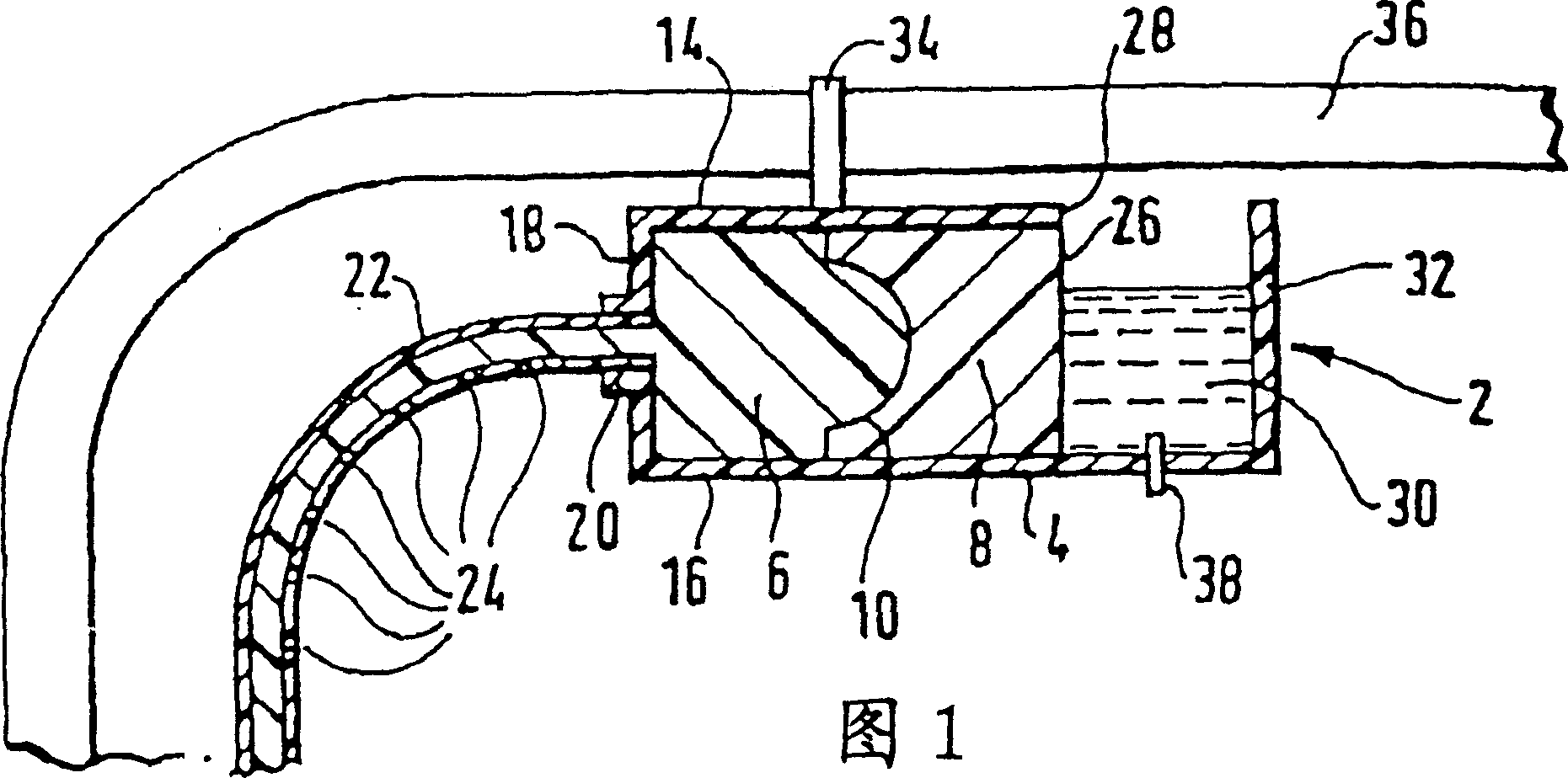
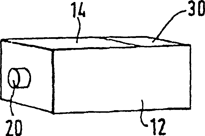
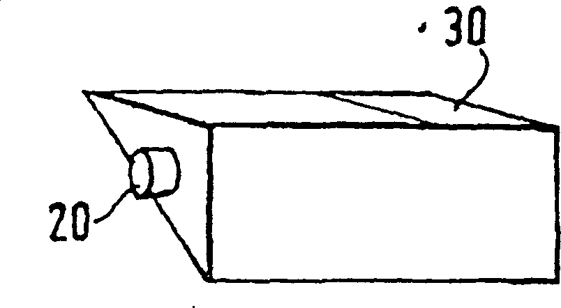
[0032] Referring to FIG. 1 , the dispensing device comprises a housing 2 . The housing 2 contains a shell 4 molded from synthetic plastics and defines two compartments 6 and 8 separated by a flexible, watertight membrane 10 . Usually each compartment is closed. The compartment 6 is surrounded by the side wall 12, the top wall 14 and the bottom wall 16 of the housing 4, the watertight membrane 10 and the end wall 18 of the housing. However, the end wall 18 of the compartment 6 facing away from the membrane 10 has an outlet 20 leading to a delivery pipe 22 . Tube 22 contains a series of delivery orifices 24 distributed along the length of tube 22 . For clarity, the distal end of the tube 22 is not shown, but it is a closed end. The only exit path for the tube is then the delivery orifice 24 .

[0033] The compartment 8 is surrounded by the side wall 12 , the top wall 14 and the bottom wall 16 of the housing, the water-tight membrane 10 and the relatively inflexible semi-wate...


PUM


Abstract

A dispensing device comprises a body (4) defining compartments (6) and (8) separated by a flexible impermeable membrane (10). Compartment (8) is closed off by a semi-permeable membrane (26) adjacent which a water container (30) is disposed. An apertured delivery tube (22) leads from compartment (6). The device may be used to dispense a cleaning, disinfectant and / or fragrancing gel into a toilet bowl. On flushing, water enters the container (30) and migrates through the membrane (26) increasing the pressure in an osmotic agent or swellable hydrogel in compartment (8). This imposes a pressure on flexible membrane (10) to displace gel from compartment (6) into the toilet bowl through apertures (24) in tube (22).

Description

technical field [0001] The present invention relates to a dispensing device for dispensing articles into a toilet bowl. The device can be used to dispense any desired material into a toilet bowl, such as cleaners, sanitizers, fragrances, colorants, detergents, or any mixture thereof, or any other hygienic benefit material. The device can be placed in the toilet bowl as desired and functions when the toilet is flushed. Background technique [0002] The device uses osmosis to provide delivery power. It is known to utilize osmosis in dispensing items. Two such devices are described in WO 94 / 23765 and WO 96 / 41621. In both devices, the air freshener is continuously introduced onto the surface to diffuse into the environment by evaporation. This requires intermittent provision of the active agent to the aqueous environment, such as a flush toilet. Neither device is suitable for this purpose. It is an object of the present invention to provide a dispensing device that meets t...

Claims


Application Information

Patent Timeline
IPC IPC(8): E03D9/03
CPCE03D9/032
Inventor 杰弗里·罗伯特·哈蒙德马尔科姆·汤姆·麦基奇尼斯蒂文·波伊利
Owner RECKITT BENCKISER (UK) LTD
Features
  • R&D
  • Intellectual Property
  • Life Sciences
  • Materials
  • Tech Scout
  • Unparalleled Data Quality
  • Higher Quality Content
  • 60% Fewer Hallucinations
Learn More