
Internal and external double-channel fin tube and heat exchange using said fin tube

A finned tube and double-channel technology, applied in the field of heat exchangers, can solve the problems of increased metal consumption on non-heat exchange surfaces, reduction of heat transfer coefficient and efficiency of heat exchangers, troublesome calculation of heat transfer and resistance of heat exchangers, etc. , to improve the accuracy of heat transfer and resistance calculation, compact structure, and solve the effect of heat leakage

Inactive Publication Date: 2004-11-24
吕钢岭 +2
View PDF0 Cites 0 Cited by
  • Summary
  • Abstract
  • Description
  • Claims
  • Application Information

AI Technical Summary

Problems solved by technology

In the heat exchanger using the above-mentioned finned tubes, one fluid flows in the tube side and inside the tube, and the other fluid flows in the shell side and between the tubes. Baffles and / or longitudinal baffles, when installing transverse baffles, the process arrangement is cross-flow, when installing longitudinal baffles, the process arrangement is baffles, compared with the pure counter-flow arrangement, the average heat transfer temperature difference Reduced, in heat exchangers with transverse baffles, there are inevitably bypass gaps between the finned tubes and the shell, between the baffles, the shell and the finned tubes, resulting in internal leakage
In the heat exchanger with longitudinal baffles, there is also internal leakage, and there is also heat leakage, which seriously reduces the heat transfer coefficient and efficiency of the heat exchanger, not only increases the metal consumption of the non-heat exchange surface, but also gives the heat exchanger The calculation of heat transfer and resistance has brought a lot of trouble, and there is no accurate calculation method so far
In addition, when the shell side is a high-temperature and high-pressure working medium, a very thick shell is required, and the metal consumption on the non-heat exchange surface of the entire heat exchanger is greatly increased, resulting in a great waste of materials

Method used


Image

  • Internal and external double-channel fin tube and heat exchange using said fin tube
  • Internal and external double-channel fin tube and heat exchange using said fin tube
  • Internal and external double-channel fin tube and heat exchange using said fin tube

Examples


Embodiment Construction

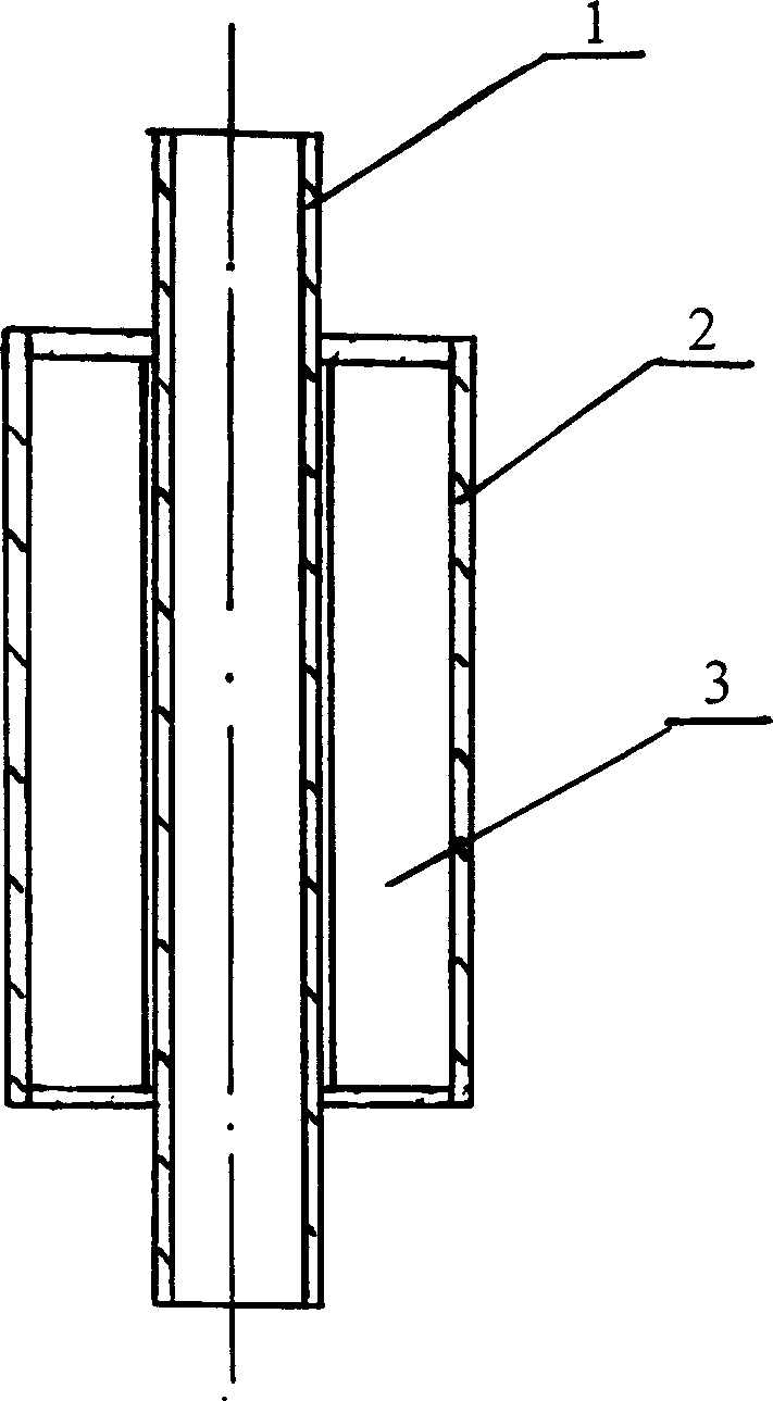
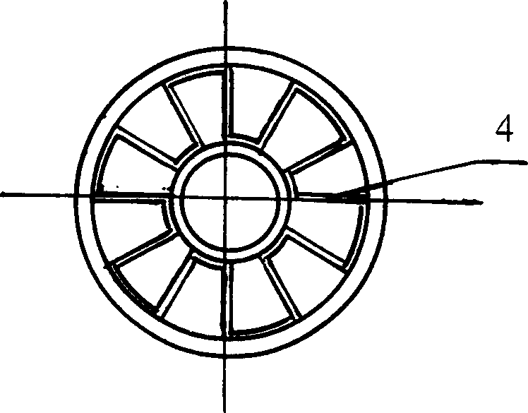
[0018] figure 1 , figure 2 It shows an embodiment of the finned tube with inner and outer double channels of the present invention. The finned tube is made of two kinds of circular tubes with different diameters nested together, and folded fins 5 are arranged in the annular channel between two adjacent tubes 1 and 2 , the circular channel in the inner hole of tube 1 is the inner channel, and the annular channel between tube 1 and tube 2 is the outer channel. In order to isolate the inner and outer channels conveniently, the inner channel is longer than the outer channel, and the longer part flows Both ends of the channel extend outwards to realize a type of finned tube with internal and external channels of the present invention.

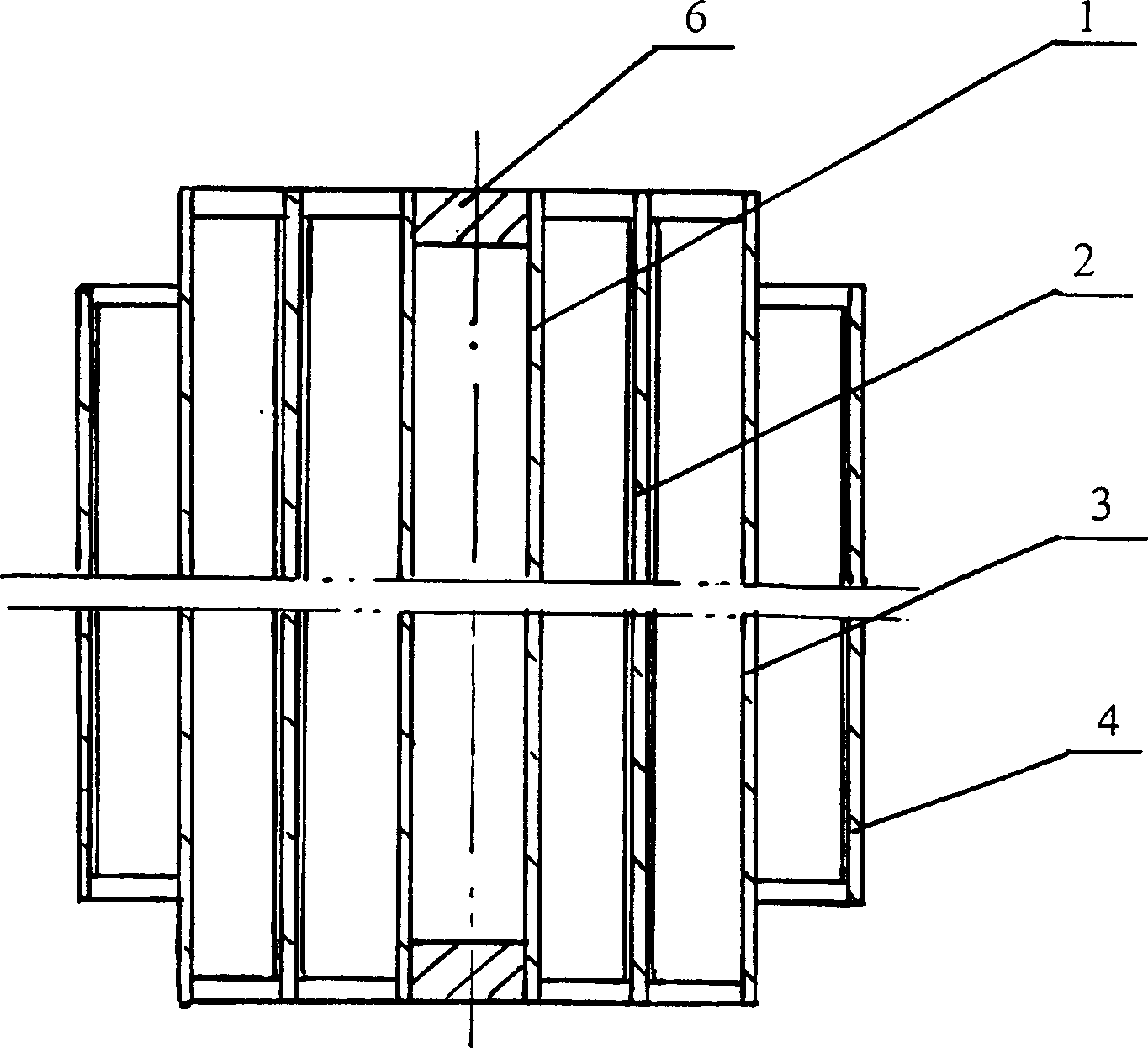
[0019] image 3 , Figure 4 Another embodiment of the finned tube with internal and external channels of the present invention is shown. The finned tube has four circular tubes of different diameters nested together, tube 1 and tube 2, tube 2 an...


PUM


Abstract

The present invention discloses a kind of inner and outer double runner fin tube and heat exchanger using said fin tube. Said invented fin tube is formed from at least two kinds of tubes with different diameters which are mutually cover-mounted together, in the annular channel formed from adjacent tubes the high-efficiency compact fins are distributed. Said invention fin tube heat exchange is equipped with several fin tubes with inner and outer double runner, the inner runner and outer runner respectively aodpts parallel-connection, series-connection or parallel-series mixed connection mode, and separated into two or more than two heat-exchanging cavities. Said invented fin tube and its heat exchanger are comdpact in structure and high in heat exchange efficiency, and can be extensively applicable to heat exchange between gas-gas, gas-liquid and liquid-liquid media.

Description

technical field [0001] The invention discloses a finned tube with internal and external double channels and a heat exchanger using the finned tube, which are widely used in the heat exchange of gas-gas, gas-liquid and liquid-liquid media. Background technique [0002] In order to improve the heat transfer coefficient of the heat exchanger, increase the area of ​​the heat exchanger, and improve the efficiency and compactness of the heat exchanger, fins (or fins) are often added to the inner and outer walls of the heat exchanger. Finned tubes currently used in heat exchangers can be roughly divided into two categories: one is outer finned tubes, which include coiled finned tubes, sleeved finned tubes and integrally rolled finned tubes, etc.; the other is outer finned tubes. One type is the inner finned tube. This type of finned tube is to add fins on the inner wall of the heat exchange tube, such as drawing a longitudinal inner rib parallel to the axis of the heat exchange tub...

Claims


Application Information

Patent Timeline
Patent Type & Authority Patents(China)
IPC IPC(8): F28D7/06F28D7/10
Inventor 吕钢岭
Owner 吕钢岭
Learn More