Device for implanting lens into eye

A technology for embedding devices and lenses, which can be used in intraocular lenses, eye implants, prostheses, etc., and can solve problems such as difficult orientation and unexpectable vision

Inactive Publication Date: 2005-02-09
杉浦毅
View PDF0 Cites 0 Cited by
  • Summary
  • Abstract
  • Description
  • Claims
  • Application Information

AI Technical Summary

Problems solved by technology

[0009] The biggest disadvantage common to both extraocular and intraocular methods is that the needle 24 or 26 is difficult to guide correctly in the ciliary sulcus 22
Furthermore, good vision cannot be expected if the aforementioned contacts 18 do not fit correctly in the ciliary sulcus 22

Method used


Image

  • Device for implanting lens into eye
  • Device for implanting lens into eye
  • Device for implanting lens into eye

Examples


Embodiment Construction

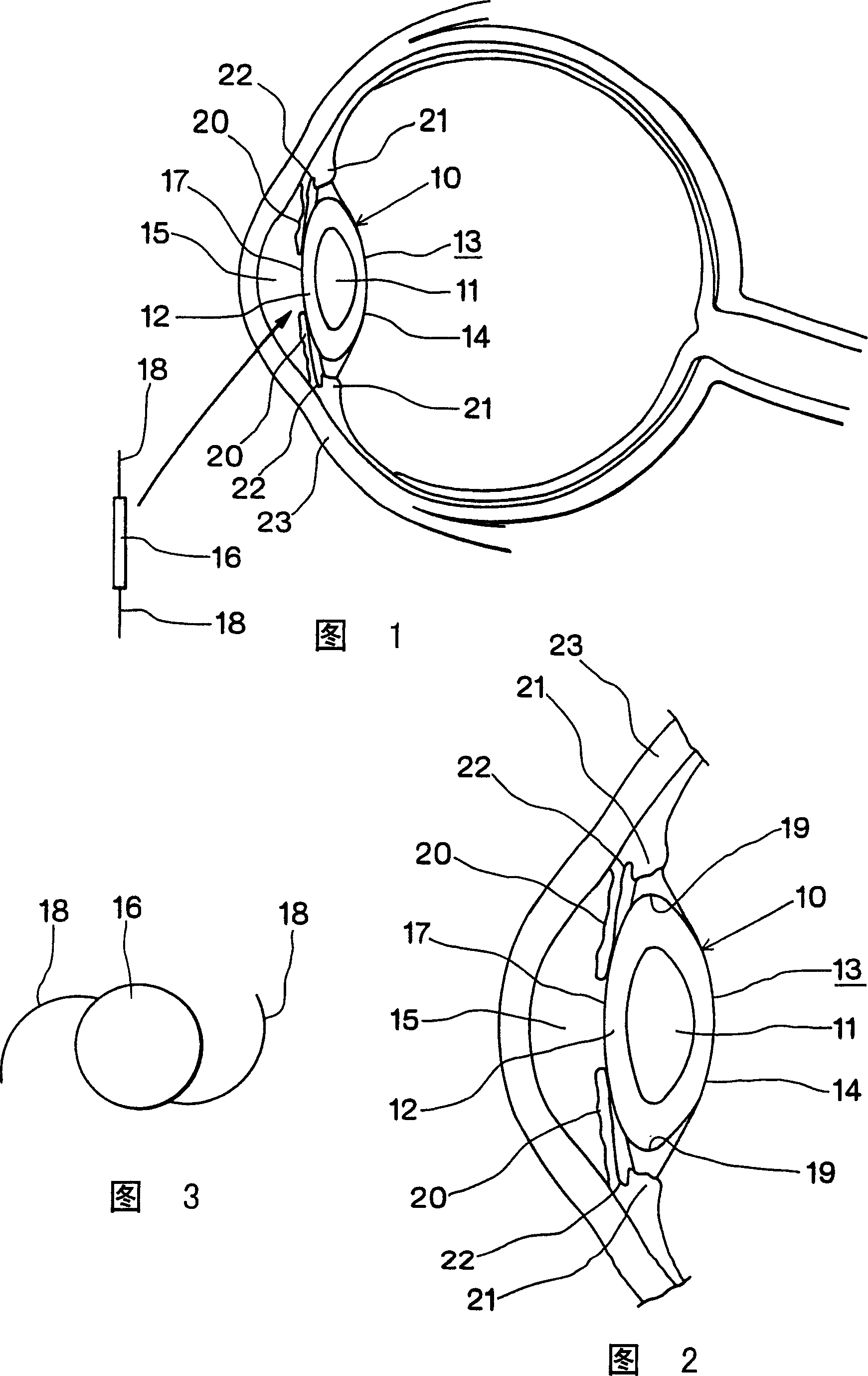
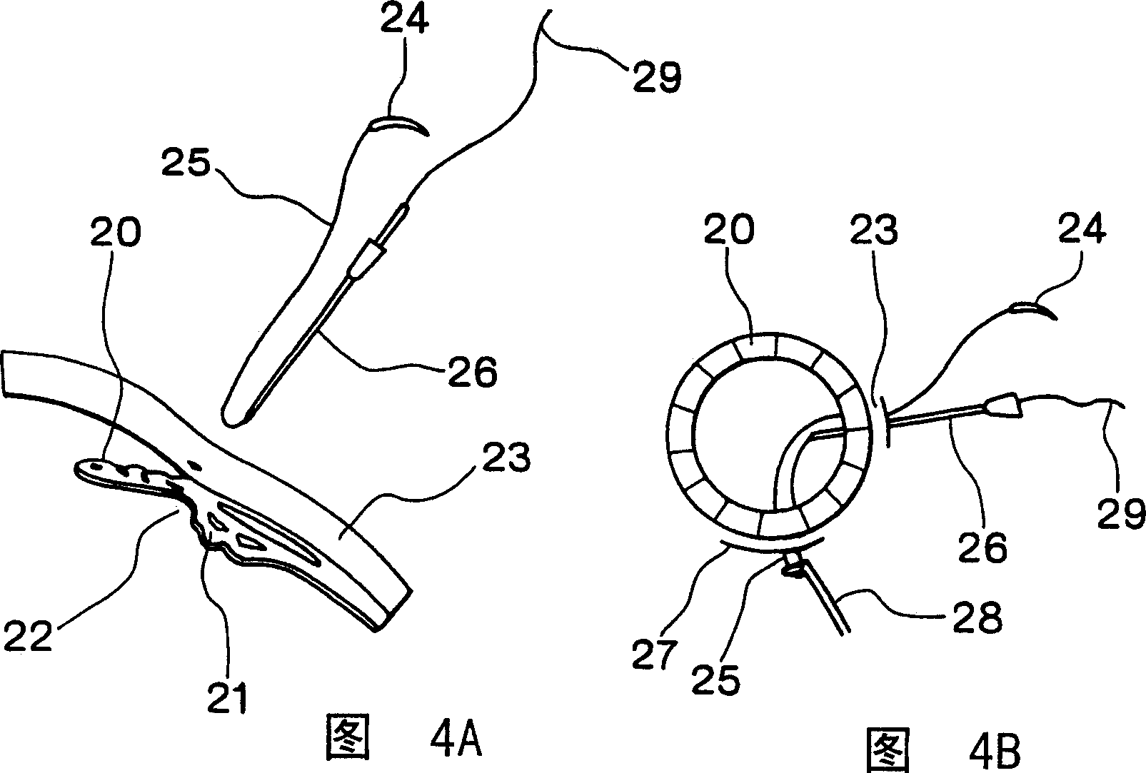
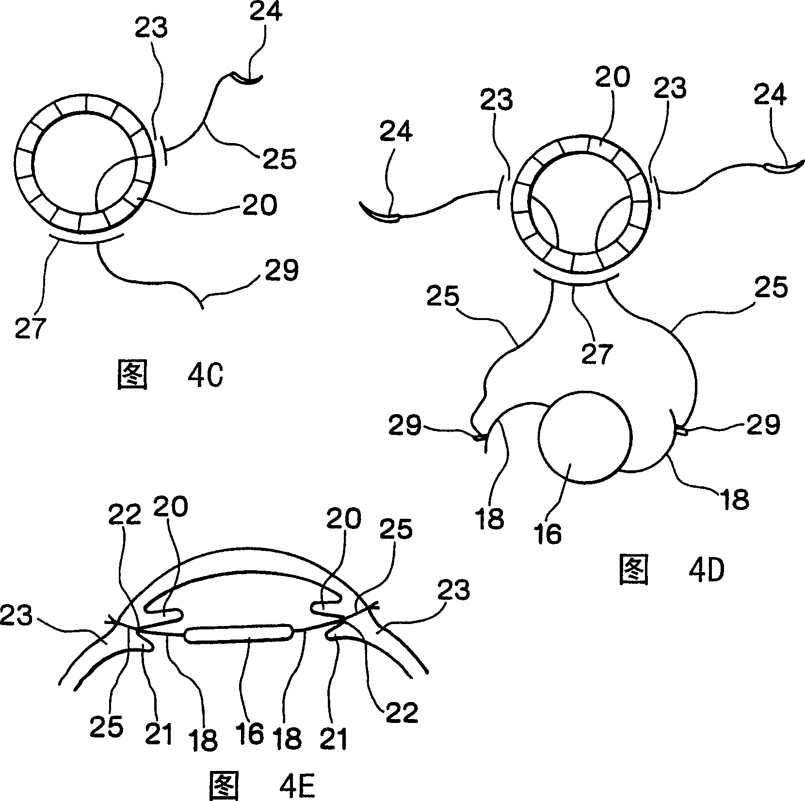
[0022] Embodiments of the present invention will be described below with reference to the accompanying drawings. As shown in Figures 6 to 8, the intraocular lens embedding device of the present invention is composed of a spacer 50 and a lead wire 51. The spacer 50 is formed by an elastic body that is harmless to the human body such as silicon rubber or silicon sponge. The back of the spacer 50. The insertion device described above is used when the posterior lens 16 is attached to the portion supporting the posterior chamber lens 16 , that is, the eyeball without the phakic capsule 13 .

[0023] Viewed from a plane, the gasket 50 is basically fan-shaped. As shown in FIG. 7 , the top surface 52 of the gasket 50 is basically a flat surface. A front inclined surface 53' of the bottom surface 53 of the spacer 50 is inclined toward the top surface 52, and a tapered insertion portion 54 is formed here. The spacer 50 has a thickness of 1.0 to 2.0 mm at the thickest middle portion. ...


PUM

PropertyMeasurementUnit
lengthaaaaaaaaaa
thicknessaaaaaaaaaa

Abstract

An intraocular lens insertion device comprises a pad formed by an elastic element harmless to a living body, a drawing thread mounted on a rear portion of the pad, and an insert portion formed at a front portion of the pad. The insert portion has a shape suitable to fit into a ciliary sulcus of an aphakic eye. The pad has a thickness capable of covering a tip end of a surgical needle.

Description

technical field [0001] The present invention relates to intraocular lens insertion devices, and more particularly to posterior chamber lens insertion devices, for use in aphakic eyes in which the posterior capsule of the lens has been removed or lost due to cataract surgery, accidents, injuries, etc. Posterior chamber lens. Background technique [0002] In the past, the cloudy lens caused by cataracts was removed with surgical devices. As shown in FIGS. 1 and 2 , the lens 10 has a nucleus 11 and a cortex 12 , and the whole is covered by a lens capsule 13 . In the period when the intraocular lens is not developed, the whitish and cloudy lens 10 is removed together with the entire lens capsule 13 by ICCE (Intracapsular Cataract Extraction), or the posterior capsule 14 in the remaining lens capsule 13 is removed by ECCE (Entracapsular Cataract Extraction). case is removed. During cataract surgery during this period, the intraocular lens could not b...

Claims


Application Information

Patent Timeline
Patent Type & Authority Patents(China)
IPC IPC(8): A61F9/007A61B19/00A61F2/14A61F2/16A61L27/00
CPCA61B2019/481A61F2/1662A61B2090/08021
Inventor 杉浦毅
Owner 杉浦毅
Why Eureka
Try Eureka