Connector for printed wiring board

A technology for printed wiring boards and connectors, which is applied to printed circuit components, structural connections of printed circuits, printed circuits, etc., and can solve problems such as easy wear, easy deformation of the shell, and reduced connection strength between the shell and the skeleton.

Inactive Publication Date: 2005-03-09
JST MFG CO LTD
View PDF1 Cites 2 Cited by
  • Summary
  • Abstract
  • Description
  • Claims
  • Application Information

AI Technical Summary

Problems solved by technology

And, the elastic convex body that is made of such hard synthetic resin, contacts with the side surface of housing and wears easily, reduces the connection strength of housing and frame as a result.
[0009] On the one hand, in order to achieve thinning, only the shell constitutes the part of the outer profile as in the above-mentioned publication, and there are concerns about warping of the shell and other deformations.
Especially through the socket connector plugged in the plugging space, when the shell is pried, the shell is easily deformed

Method used


Image

  • Connector for printed wiring board
  • Connector for printed wiring board
  • Connector for printed wiring board

Examples


Embodiment

[0029] Hereinafter, preferred embodiments of the present invention will be described with reference to the accompanying drawings.

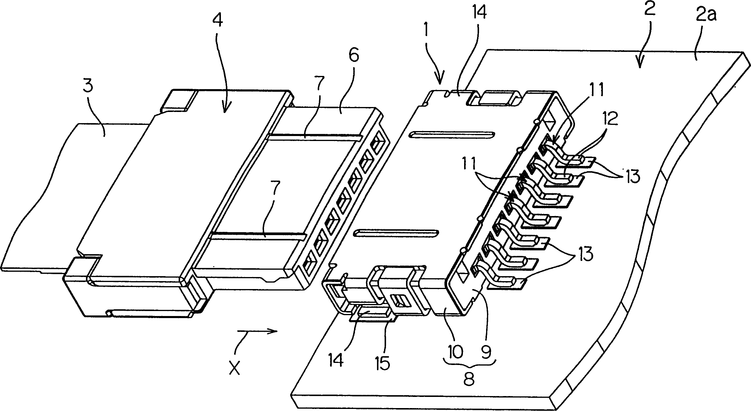
[0030] refer to figure 1 , the base connector 1 is arranged along the surface of the printed wiring board 2, and is connected to the opposite socket connector 4 connected to the end of the flexible printed circuit board 3 called FPC. The socket connector 4 has an insertion space 5 (refer to Image 6 ) The insertion protrusion 6 for insertion and extraction. A pair of left and right grooves 7 extending parallel to the insertion direction X of the socket connector 4 are formed on the upper surface of the insertion protrusion 6 .

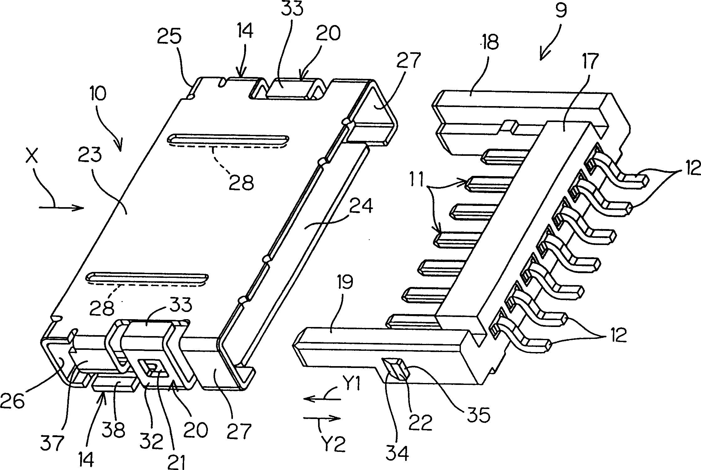
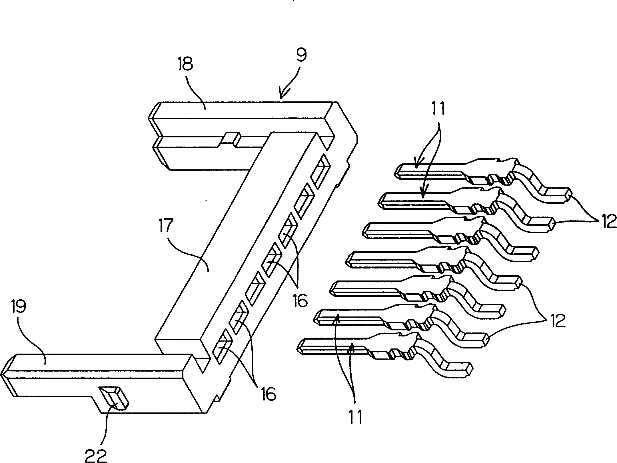
[0031] refer to figure 1 and figure 2 The base connector 1 includes a connector body 8 having a frame 9 made of synthetic resin and a shell 10 serving as an electromagnetic shield made of a thin metal plate.

[0032] refer to figure 1 The base connector 1 is fixed by soldering the reeds 12 of the exposed contacts 11...


PUM


Abstract

A connector includes a connector body having an insertion space for receiving its counterpart connector. The connector body includes a synthetic-resin housing for retaining contacts, and a metallic shell. A part of the insertion space is defined by an upper plate of the shell. The upper plate of the shell has extensions extended therefrom along corresponding side walls of the housing. The extensions include legs soldered to a conductive portion on a printed wiring board surface. The legs are outwardly extended and confined in an outline of the connector body as viewed in plan.

Description

technical field [0001] The present invention relates to an electrical connector mounted on a printed wiring board. Background technique [0002] Such a connector is usually covered around a synthetic resin frame with an electromagnetic shielding case. Since the shell is made of metal, it helps to increase the strength of the connector. [0003] Furthermore, when such a connector is applied to a small electronic device such as a mobile phone, it is required to be small and thin. [0004] In order to achieve thinning, there is JP-A No. 10-270125 (published on October 9, 1998). [0005] The connector of the above-mentioned publication divides the top of the plug-in space through the upper plate of the housing. In other words, a part of the frame made of resin is missing, and the outer shell of this part is composed only of the shell. [0006] However, since the housing is formed of a thin plate, there is a fear of weakening the strength of the connector. Therefore, reinfor...

Claims


Application Information

Patent Timeline
Patent Type & Authority Patents(China)
IPC IPC(8): H01R9/16H01R12/57H01R12/71H01R13/506H01R13/658H01R13/6594H01R24/00H05K1/14H05K3/34
CPCH05K3/341H01R12/57H01R13/658H01R13/6594H01R13/506H01R23/7073H01R12/716H01R9/16
Inventor 黑田桂治新本清
Owner JST MFG CO LTD
Why Eureka
Try Eureka