Plasma display

A plasma and display technology, used in static indicators, instruments, cold cathode tubes, etc., can solve the problems of thin design that cannot be used with PDP displays, and the large size of rupture detection sensors.

Inactive Publication Date: 2005-06-01
AU OPTRONICS CORP
View PDF0 Cites 0 Cited by
  • Summary
  • Abstract
  • Description
  • Claims
  • Application Information

AI Technical Summary

Problems solved by technology

However, the crack detection sensor cannot be used in the thin design of the PDP display due to its large volume.

Method used


Image

  • Plasma display
  • Plasma display
  • Plasma display

Examples


Embodiment Construction

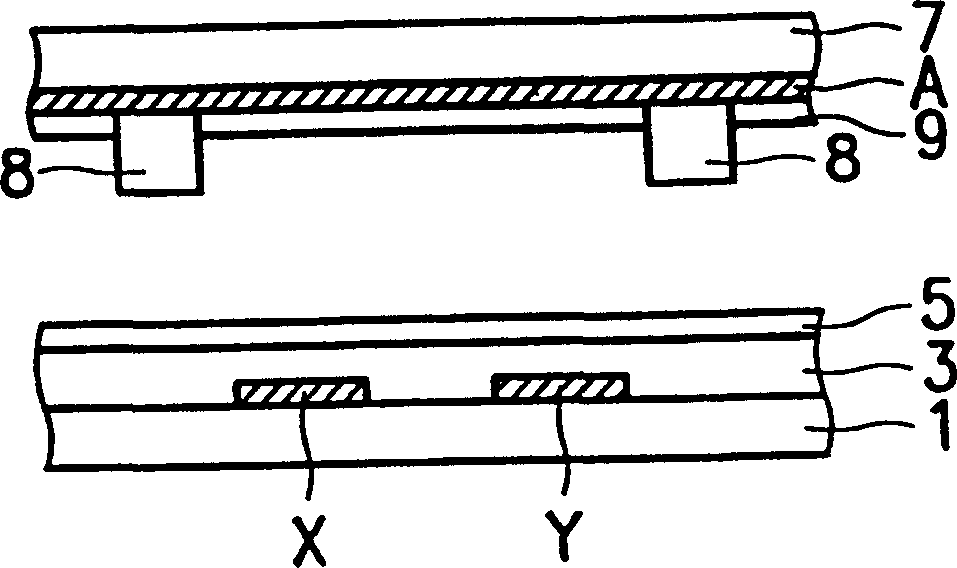
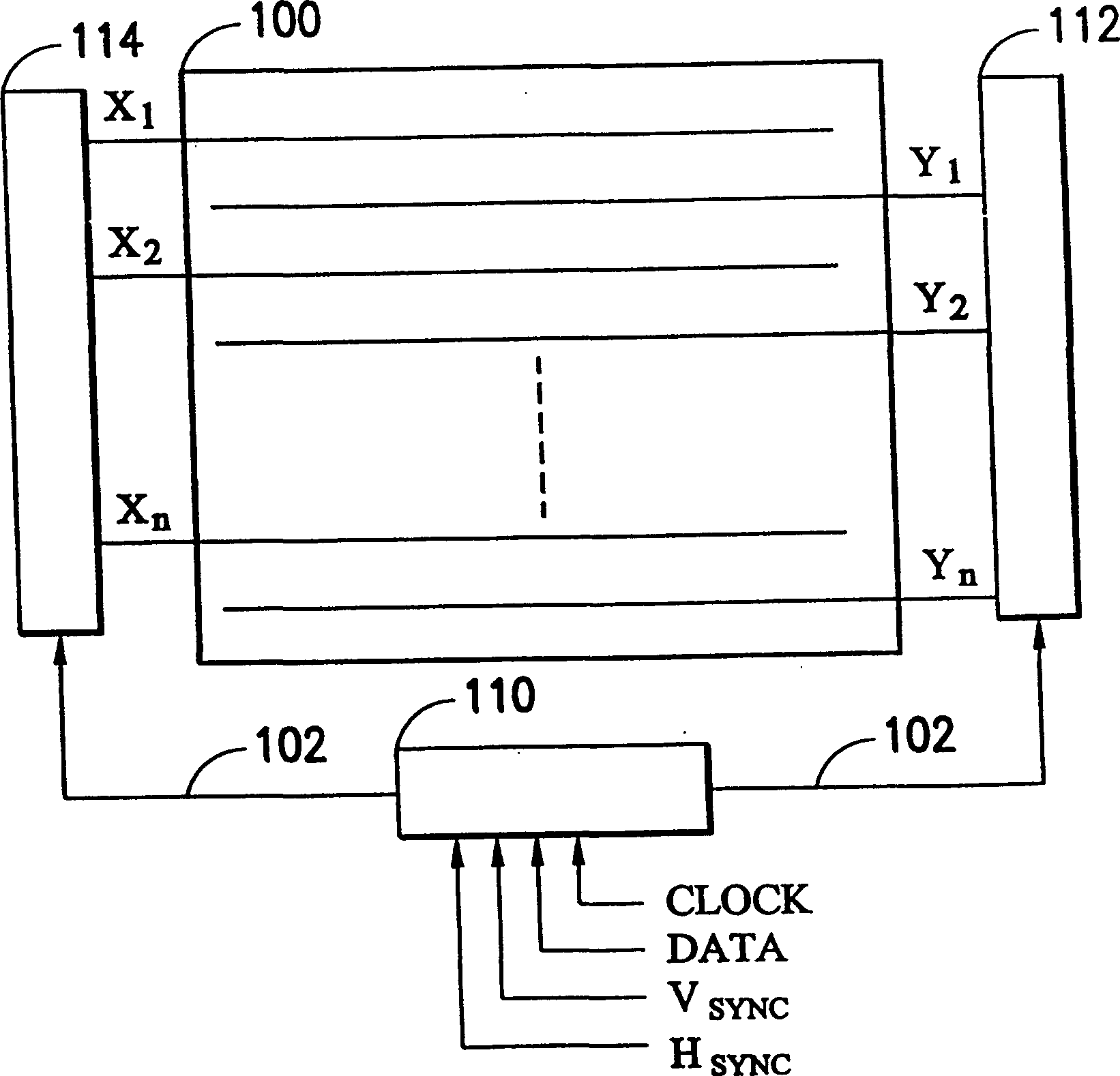
[0024] reference Figure 5 versus Figure 8 , Figure 5 This is a schematic diagram of a plasma display in this embodiment; Figure 8 This is a schematic cross-sectional view of the display unit 10 in the plasma display (PDP) of this embodiment.

[0025] Such as Figure 8 As shown, the plasma display is composed of a front substrate 1'and a rear substrate 7'. The front plate 1'includes scan electrodes Y'and sustain electrodes X'parallel to each other, a detection wire L1, a dielectric layer 3', and a protective film 5'. The rear plate 7'includes address electrodes A', partition walls 8'(partition walls) on both sides of the address electrodes, and fluorescent materials 9'between the barrier walls 8'. The plasma display includes a plurality of pixels 10. When a bias voltage is applied between the sustain electrode X'and the scan electrode Y', the pixels 10 can be discharged to make the plasma display display images.

[0026] reference Figure 5 , The front plate 1'of the plasma dis...


PUM


Abstract

A plasma display with multiple pixels. The plasma display includes a front panel on which a plurality of sustain electrodes and a plurality of scan electrodes are disposed. When a bias voltage is applied between the plurality of sustain electrodes and the plurality of scan electrodes, the plurality of pixels can perform discharge operations. , the front plate also has a first side and a second side, and the two sides are opposite; the rear plate is opposite to the front plate and has a plurality of address electrodes; the scan driver is arranged on the first side; the detection and reception circuit is arranged on the third side. Two sides; the detection wire is provided on the front panel, the detection wire has a first and a second end, the first end is coupled to the scan driver and the second end is coupled to the detection receiving circuit; and the control circuit is coupled to the scan Driver and detection receiving circuit.

Description

Technical field [0001] The invention relates to a method and system for detecting glass breakage, in particular to a plasma display with a method and system for detecting glass breakage. Background technique [0002] figure 1 A schematic cross-sectional view showing the cell structure of a plasma display panel (PDP for short) in the prior art. As shown in the figure, the plasma display is composed of a front substrate 1 and a rear substrate 7. The front plate 1 includes scan electrodes Y and sustain electrodes X, a dielectric layer 3, and a protective film 5 that are parallel to each other. The rear plate 7 includes address electrodes A and a fluorescent material 9 thereon. A partition wall 8 is used to isolate the surroundings of each unit. [0003] figure 2 Indicates the use figure 1 The block diagram of the plasma display composed of the PDP shown. As shown in the figure, the PDP 100 is composed of scan electrodes Y parallel to each other 1 ~Yn and sustain electrode X 1 ~...

Claims


Application Information

Patent Timeline
IPC IPC(8): G09G3/288
Inventor 蔡宗光
Owner AU OPTRONICS CORP
Why Eureka
Try Eureka