Voltage-controlled oscillator

A technology of voltage controlled oscillator and ring oscillator, applied in power oscillator, automatic power control, electric pulse generator circuit, etc., can solve the problem of impossible to obtain voltage gain, etc.

Inactive Publication Date: 2004-08-11
RENESAS ELECTRONICS CORP
View PDF1 Cites 0 Cited by
  • Summary
  • Abstract
  • Description
  • Claims
  • Application Information

AI Technical Summary

Problems solved by technology

However, when the non-inverting output voltage is high, the paired differential transistors 124 and 125 are not saturated, making it impossible to obtain the desired voltage gain

Method used


Image

  • Voltage-controlled oscillator
  • Voltage-controlled oscillator
  • Voltage-controlled oscillator

Examples


Embodiment Construction

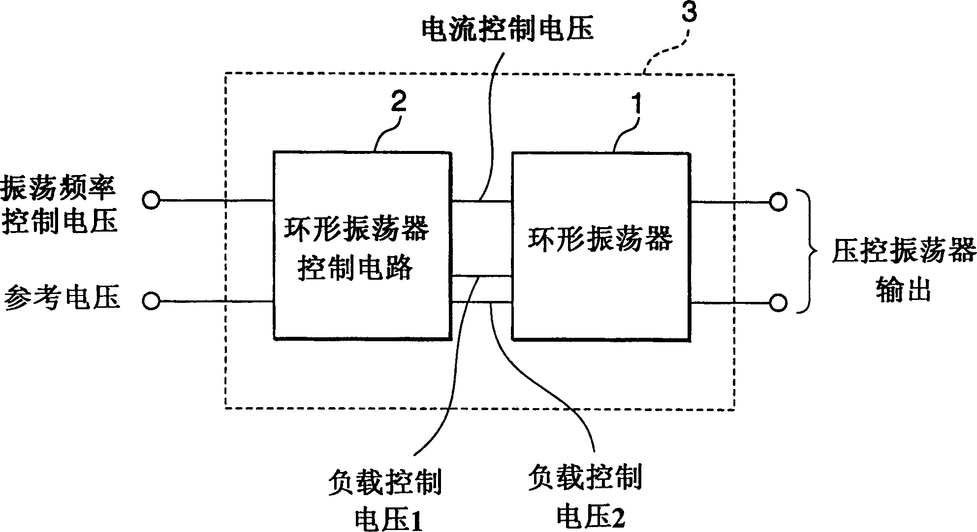
[0040] The following will refer to figure 1 The voltage controlled oscillator according to the first embodiment of the present invention will be described.

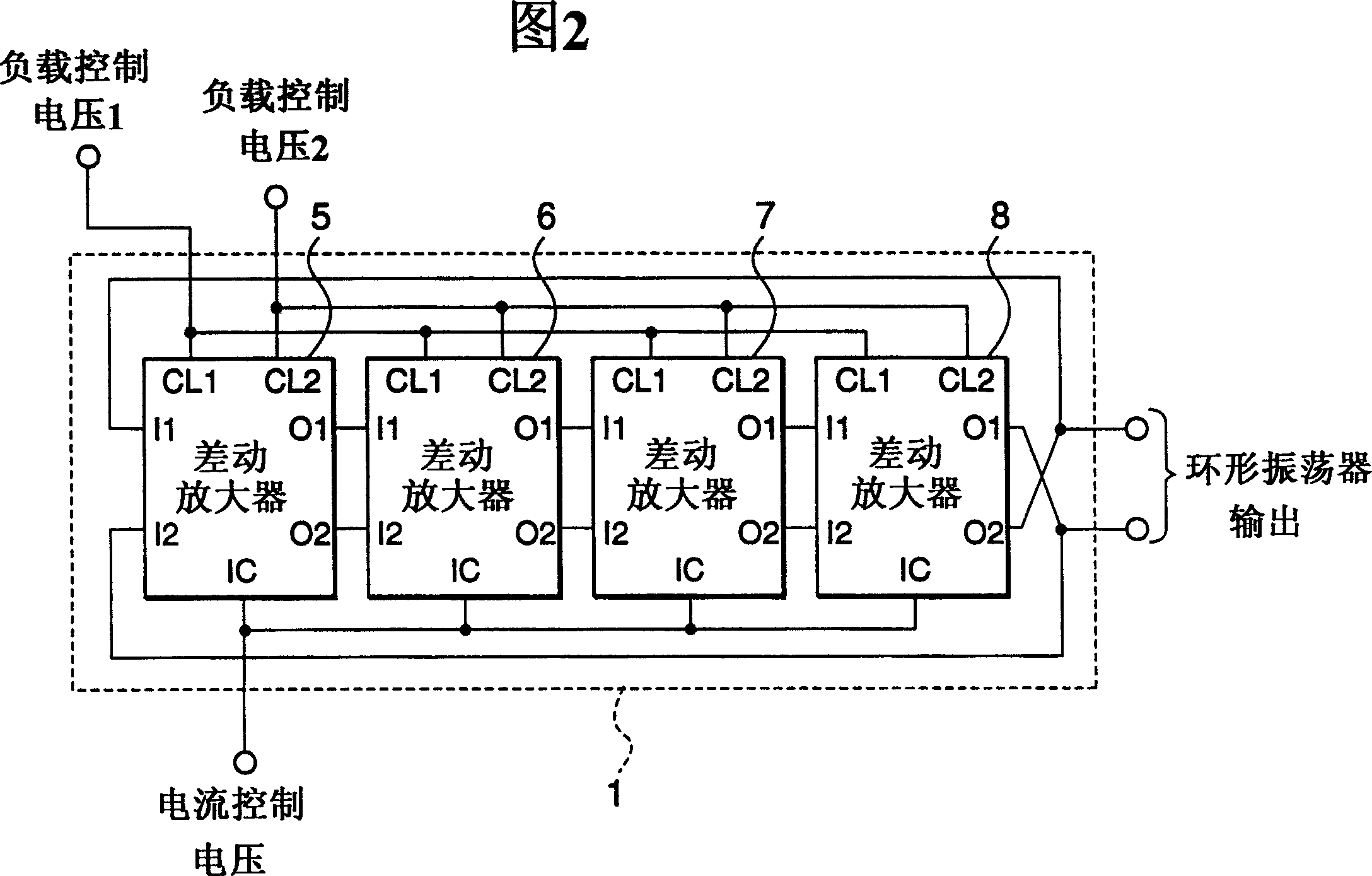
[0041] exist figure 1 Among them, the voltage-controlled oscillator 3 includes a ring oscillator control circuit 2 loaded with an oscillation frequency control voltage and a reference voltage and a current control voltage output by the ring oscillator control circuit 2 loaded thereon and A load controls voltages 1 and 2 for ring oscillator 1. The output of the ring oscillator 1 becomes the output of the voltage-controlled oscillator 3 . Figure 2 is figure 1 The circuit diagram of Ring Oscillator 1 is shown. Ring oscillator 1 is made up of a plurality of differential amplifiers, in the present embodiment, ring oscillator 1 is made up of four differential amplifiers 5 to 8, wherein each differential amplifier all contains a positive input terminal I1, a negative input terminal I2, a positive output terminal O1, a ne...


PUM


Abstract

A voltage-controlled oscillator 3 is constructed with a ring oscillator control circuit 2 and a ring oscillator 1, which is constructed with a plurality of differential amplifiers 5 to 8 each including a differential pair of transistors 24 and 25 and load circuits 22 and 23 connected to the respective transistors. The load circuits 22 and 23 are constructed such that the differential amplifiers always operate in linear region according to load drive voltages CL1 and CL2.

Description

technical field [0001] The invention relates to a voltage-controlled oscillator. More specifically, the present invention relates to a voltage controlled oscillator comprising a ring oscillator consisting of a plurality of differential amplifiers with load circuits. Background of the invention [0002] In a modern phase-locked loop (PLL) used in a CD-ROM disc servo system, etc., the output frequency range needs to be up to several times to ten times the reference oscillation frequency of the PLL. As we all know, the PLL contains a voltage-controlled oscillator whose output frequency can be changed according to the input voltage. [0003] Modern PLLs all have an on-chip structure, because the modern trend is to increase the scale of integrated circuits and increase their operating speed. The voltage-controlled oscillator of this PLL should have a structure suitable for being integrated into a chip. That is, there is a need to develop a voltage-controlled oscillator that is...

Claims


Application Information

Patent Timeline
IPC IPC(8): H03K3/354H03K3/0231H03K3/03H03L7/099
CPCH03K3/0322H03L7/0995H03K3/03H03K3/0231H03L7/187
Inventor 谷本晋
Owner RENESAS ELECTRONICS CORP
Why Eureka
Try Eureka