Shaft lock device

A shaft locking and central shaft technology, which is applied in pivot connection, multi-purpose hand tools, faulty computer hardware detection, etc., can solve the problem of inability to determine the location of friction torque, increase of parts with friction torque, and inability to ensure friction torque and other problems, to achieve the effect of simple structure, stable friction torque and improved durability

Inactive Publication Date: 2005-07-13
NHK SPRING CO LTD
View PDF0 Cites 0 Cited by
  • Summary
  • Abstract
  • Description
  • Claims
  • Application Information

AI Technical Summary

Problems solved by technology

In this shaft locking device, when the central shaft 100 and the interactive component 120 are in relative rotation, any component may rotate with the central shaft 100, and it is impossible to determine which component rotates
Therefore, the location where the friction torque occurs cannot be identified, and the friction torque varies depending on the rotating parts
Therefore, there is a problem that a stable friction torque cannot be ensured
Moreover, the number of components used to generate friction torque increases, the structure is complicated, and the installation is cumbersome.

Method used


Image

  • Shaft lock device
  • Shaft lock device
  • Shaft lock device

Examples


Embodiment 1

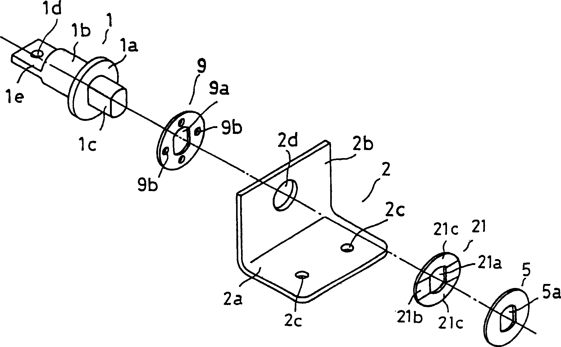
[0023] figure 1 Shown is Embodiment 1 of the present invention, which is composed of a central shaft 1, a friction plate 9, a bracket 2 as an interactive part, an elastic pressing part 21, a stop plate 5 and the like. A friction plate 9 , a bracket 2 , an elastic pressing member 21 , a stopper plate 5 and the like are mounted on the center shaft 1 . An insertion portion 1a is arranged on the central axis 1, and both sides of the insertion portion 1a start to the installation shaft portion 1b and to the connection shaft portion 1c, which extend coaxially, and the installation shaft portion 1b is installed on the display panel as a connecting part, (shown Omit) For ease of installation, a fixed hole 1d is provided at the end of the thin plate-shaped mounting piece 1e, and the connecting shaft portion 1c is where the friction plate 9, the bracket 2, the elastic pressure member 21, the stop plate 5, etc. are installed. After planing, the connecting shaft portion 1c has a non-cir...

Embodiment 2

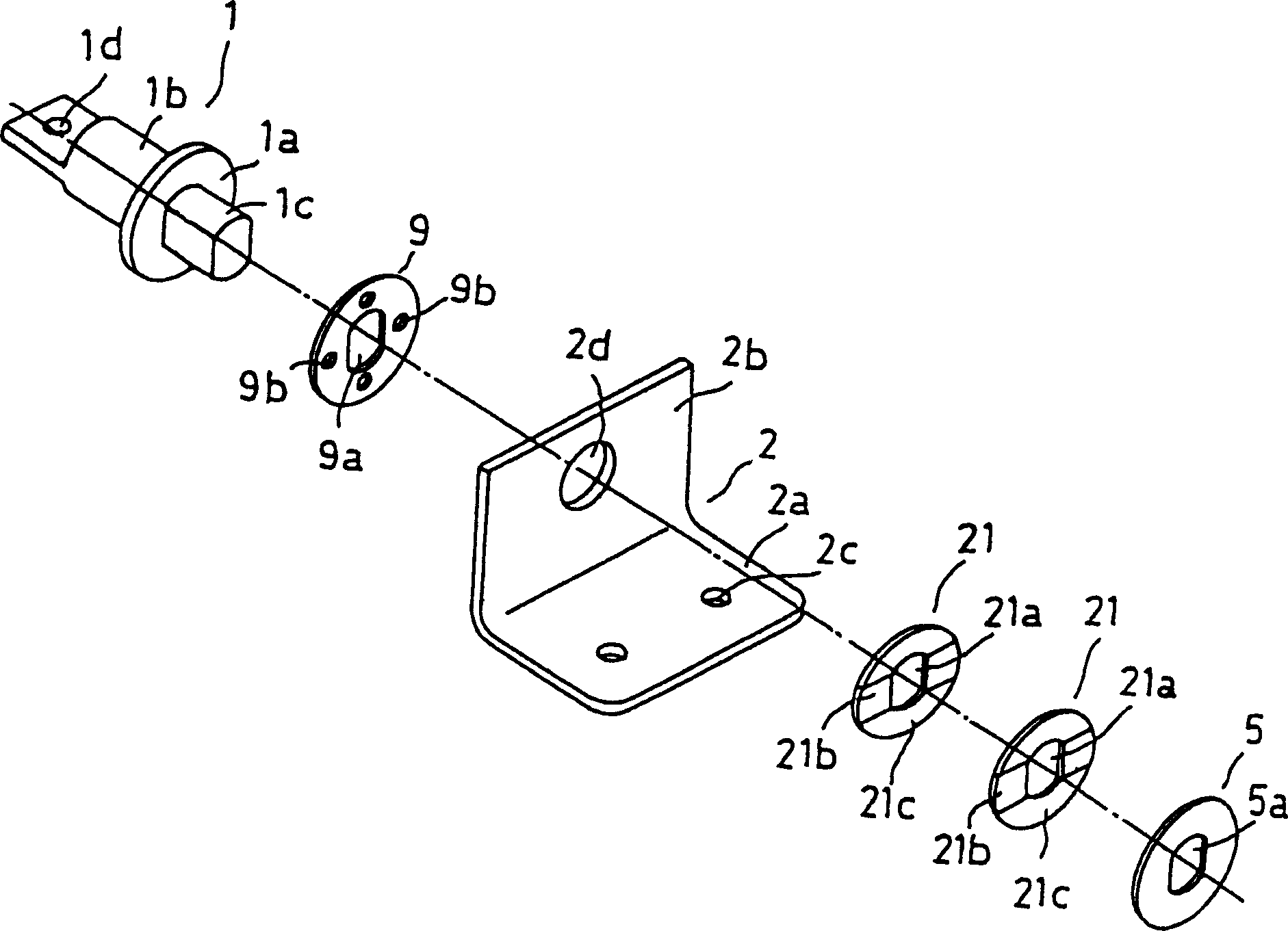
[0027] image 3 Example 2 is shown, and this example is different from the elastic pressing member in the above-mentioned example 1 in that two U-shaped springs 21 are used. These two U-shaped springs 21 overlap and are arranged between the bracket 2 and the stop plate 5. In this case, the U-shaped spring 21 on the side of the bracket 2, the bottom surface of its planar portion 21b and the bracket In this case, the protrusion 21c of the U-shaped spring 21 is in contact with the protrusion 21c of the U-shaped spring 21 on the other side along the plane portion 21b, (that is, 2 Sheet U-shaped springs 21 are staggered and overlapped). Then, the end portion of the connecting shaft portion 1c penetrating through the stopper 5 is fastened, and the two U-shaped springs 21 are alternately overlapped to apply pressure to the shaft supporting portion 2b of the bracket 2 . In this case, the two U-shaped springs 21 are arranged along the central axis, and the plurality of U-shaped sprin...

Embodiment 3

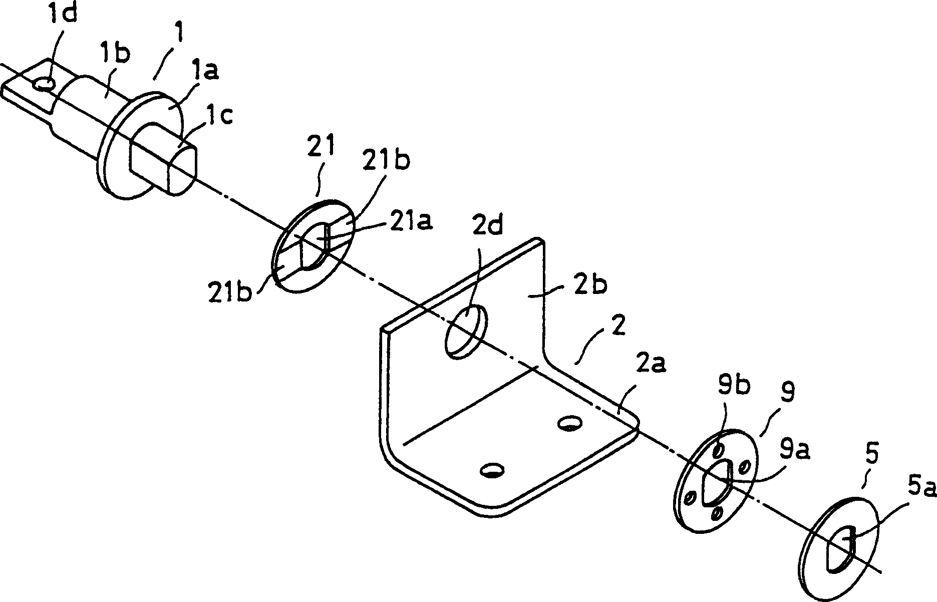
[0030] Figure 4 Example 3 is shown. In this example, the friction plate 9 in Example 1 is omitted, that is, for the bracket 2, the U-shaped spring 21, and the stopper 5, the connecting shaft portion 1c of the central shaft 1 is used to pass through it. The end is fastened, the insertion part 1a of the central shaft 1, the shaft support part 2b of the bracket 2, the U-shaped spring 21 and the stopper 5 overlap, and the friction torque generated by the direct pressure of the U-shaped spring 21 Under the action, the central axis 1 and the bracket 2 can maintain the mutual angle. In this state, friction occurs between the insertion portion 1a of the central shaft 1 and the shaft support portion 2b of the bracket 2, and the smaller the friction force, the longer the service life of these components. This structure has the advantages of easy installation and the like while reducing its weight due to fewer components.


PUM


Abstract

A shaft locking device, providing a shaft locking device that can generate stable friction torque, has a simple structure and can maintain any inclination angle, it includes a central shaft and an interactive component that the central shaft runs through in a free rotation state, and is characterized by: The shaft-penetrating elastic pressing part is provided with a band-shaped flat part of locked width and protrusions from both sides of the flat part in the same direction, and the flat part with the protrusions is in direct contact with the interactive part, from the thickness of the elastic pressing part or plate Viewed from the side, the curved central portion is in direct contact with the interactive component, and the central axis passes through the stop plate that pressurizes the interactive component by the elastic pressurizing component in a suppressed state. It works by using the stable friction torque generated when adjusting the inclination angle between the central axis and the interactive part, so that the interactive part and the central axis can maintain any angle.

Description

technical field [0001] The present invention is applied to notebook computers, notebook word processors, portable terminal equipment such as mobile offices, and imaging devices such as liquid crystal monitors. Or like various mechanical swivel covers, the shaft locking device of the component that needs to adjust the inclination angle. Background technique [0002] Such as Figure 21 As shown, this is the shaft locking device described in Japanese Utility Model Registration No. 2547422. The shaft locking device is composed of a sliding washer 110 , an interactive component 120 , a friction washer 130 , a spring washer 140 , and a stop washer 150 etc. installed on the central shaft 100 to form. Furthermore, on the interactive component 120, there is a mounting base plate 123, and the mounting base plate 123 is fixed on a device capable of moving the display panel. The central axis 100 is formed by the insertion part 101, and extends from one side of the insertion part 101, ...

Claims


Application Information

Patent Timeline
Patent Type & Authority Patents(China)
IPC IPC(8): E05D11/08G06F1/16G06F11/22G06F11/28
CPCE05D11/087E05Y2900/606G06F1/1616G06F1/1622G06F1/1681F16C11/10
Inventor 北村吉治斎藤诚绵谷栄二池田博大竹直彦
Owner NHK SPRING CO LTD
Why Eureka
Try Eureka