Binary logic gate circuit

A binary logic and gate circuit technology, applied in the field of logic gate circuits, can solve the problem of inability to perform dynamic conversion, and achieve the effect of fast running speed and high integration.

Inactive Publication Date: 2005-09-14
沈超然
View PDF0 Cites 0 Cited by
  • Summary
  • Abstract
  • Description
  • Claims
  • Application Information

AI Technical Summary

Problems solved by technology

[0002] At present, the existing logic gate circuits are generally composed of single-selection switch circuits, similar to single-pole single-throw switches (as shown in Figure 1), and the gate circuits can only be set in advance, but cannot be dynamically converted, such as; It is either an "AND gate" or an "OR gate", and the "AND gate" and "OR gate" cannot be converted according to the needs. With the rapid development of integrated circuits, the operating speed of logic circuits and the diversity of logic results The requirements are getting higher and higher, and the traditional single-selection switch circuit can no longer meet the demand, so someone proposed to use a bidirectional switch circuit in the digital-to-analog converter to stabilize the output value, but the bidirectional switch The two input values ​​of the circuit are both fixed values, and no one has proposed to use a similar bidirectional switch circuit in the logic gate circuit to form a binary logic gate circuit.

Method used


Image

  • Binary logic gate circuit
  • Binary logic gate circuit
  • Binary logic gate circuit

Examples


Embodiment Construction

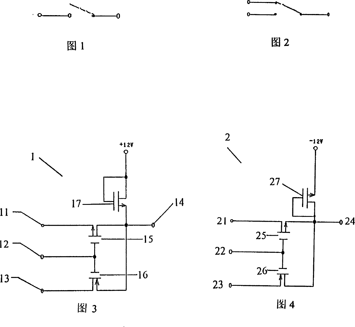
[0018] The first dual selection basic switch circuit 1 shown in Figure 3 is provided with three input terminals: a first input terminal 11, a second input terminal 12, a third input terminal 13, a first output terminal 14, two base poles ( The first switching element 15 and the second switching element 16 connected to the gate), in this embodiment, an N-type first field effect transistor 15 and a P-type second field effect transistor 16 are used as switching elements. The source of the field effect transistor 15 is connected to the first input terminal 11, the drain of the first field effect transistor 15 is connected to the first output terminal 14, and the drain of the second field effect transistor 16 is connected to the third input terminal 13, The source is connected to the first output terminal 14, and the second input terminal 12 is connected to the gates of the two field effect transistors. The third field effect transistor 17 is a load tube, and its grid and drain are ...


PUM


Abstract

The binary logic gate circuit includes a double-selection basic switching circuit with three input ends, one output end two switch element whose polarities are opposite, and is characterized by hat at least it also has a bisic switching circuit connected with logic gate circuit, and said basic switching circuit is equipped with two input ends, two output ends and two switch element with opposite polarity. Because the binary logic gate circuit possesses double selectivity and compatibility, so that the simple combination of the binary logic gate circuit can obtain the logic gate circuit more than unary logic gate circuit, besides, the "either-or" property in the double-selection can obtain several logic results, it possesses dynamic selectability and writability, and can provide more hardware support for development of computer.

Description

technical field [0001] The present invention relates to a logic gate circuit, in particular to a binary logic gate circuit composed of a double-selection basic switch circuit Background technique [0002] At present, the existing logic gate circuits are generally composed of single-selection switch circuits, similar to single-pole single-throw switches (as shown in Figure 1), and the gate circuits can only be set in advance, but cannot be dynamically converted, such as; It is either an "AND gate" or an "OR gate", and the "AND gate" and "OR gate" cannot be converted according to the needs. With the rapid development of integrated circuits, the operating speed of logic circuits and the diversity of logic results The requirements are getting higher and higher, and the traditional single-selection switch circuit can no longer meet the demand, so someone proposed to use a bidirectional switch circuit in the digital-to-analog converter to stabilize the output value, but the bidire...

Claims


Application Information

Patent Timeline
Patent Type & Authority Patents(China)
IPC IPC(8): H03K19/094H03K19/20
Inventor 沈超然
Owner 沈超然
Why Eureka
Try Eureka