Picture heating device and controller

A heating device and image technology, applied in the direction of electric heating devices, temperature control using digital devices, temperature control, etc., can solve problems such as components are prone to smoke or catch fire

Inactive Publication Date: 2005-10-12
CANON KK
View PDF0 Cites 0 Cited by
  • Summary
  • Abstract
  • Description
  • Claims
  • Application Information

AI Technical Summary

Problems solved by technology

Since the temperature of the components around the fixing unit is high, the components are prone to smoke or catch fire
Therefore, even if the ceramic plate of the heater is damaged due to thermal stress during abnormal operation, the electric power supply to the thick-film heat generating resistor can be cut off with certainty by the circuit device, thus preventing fire and smoke generation

Method used


Image

  • Picture heating device and controller
  • Picture heating device and controller
  • Picture heating device and controller

Examples


Embodiment Construction

[0027] With reference to the accompanying drawings, preferred embodiments of the present invention will be described below.

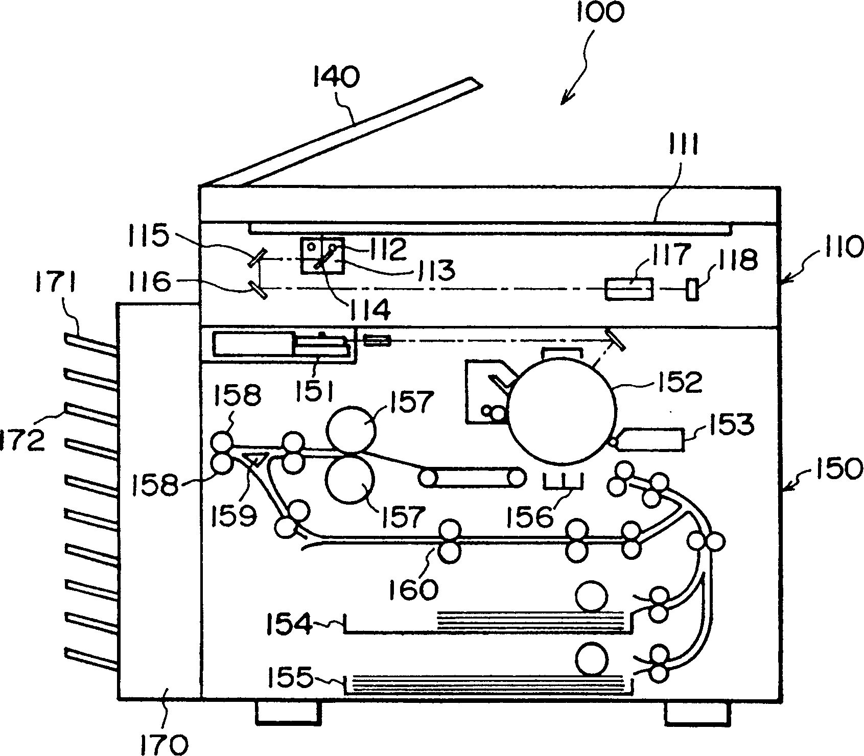
[0028] figure 1 Shown is a longitudinal sectional view of an image forming apparatus (image processing apparatus) according to an embodiment of the present invention in which an image heating device is used as a fixing device.

[0029] In the figure, a copier is indicated by reference numeral 100, and the copier includes a reading section 110 (image reading section) and a printer section 150 (image recording section).

[0030] The reading section 110 includes an original supply device 140, an original supporting platen glass 111, a scanner, a lamp 112 in the scanner section, a scanning unit 113, mirrors 114, 115, and 116, a lens 117, and a CCD image sensing section (also referred to simply as "CCD") 118 .

[0031] The printer section 150 includes an exposure controller 151, a photosensitive member 152, a developing device 153, a recording paper (copy...


PUM


Abstract

An image heating apparatus includes a heat generating element for generating heat upon electric energization; a substrate supporting the heat generating element; a temperature detecting member for detecting a temperature of the substrate; an A / D converter for A / D conversion of an output of the temperature detecting means; photo-coupling means for converting an output of the A / D converter to a light signal and outputting the light signal; and abnormality detecting means for detecting an abnormal temperature on the basis of an output of the photo-coupling means.

Description

technical field [0001] The present invention relates to an image heating device used in a fixing device of an electrophotographic type and an electrostatic recording type image forming apparatus such as a copying machine and a printer. Background technique [0002] first reference Figure 12 , which shows an example of an image heating device. [0003] Such as Figure 12 As shown, on one surface of a ceramic disc 110, a primary-side heat-generating pattern 10 (heat-generating element) is arranged. The ceramic disk 110 is a substrate mainly formed of a ceramic material. A chip thermosensitive element 104 (temperature detection part) is arranged on the other surface of the ceramic disc 110, like this, just pass through a primary side wire 108, primary side electrode 102 and main side connector 103 from the power supply to the main The heat generating plate 101 on the stage side supplies electric power, thereby generating heat. The chip thermosensitive element 104 is connect...

Claims


Application Information

Patent Timeline
IPC IPC(8): G03G15/20G05D23/24H05B3/00
CPCG03G15/2003G05D23/2422G05D23/1917G05D23/24
Inventor 木下秀彦
Owner CANON KK
Why Eureka
Try Eureka