Unlock instant, AI-driven research and patent intelligence for your innovation.

Device and method for installing component

A technology for installing devices and installing components, which is applied in the direction of assembling printed circuits, electrical components, electrical components, etc. with electrical components, and can solve problems such as errors that cannot be corrected

Inactive Publication Date: 2005-10-19
HANWHA TECHWIN CO LTD
View PDF0 Cites 0 Cited by
  • Summary
  • Abstract
  • Description
  • Claims
  • Application Information

AI Technical Summary

Problems solved by technology

Therefore, if the center point of the nozzle 15 does not correspond to the center point of the image 121 during probing, the error cannot be corrected

Method used


Image

  • Device and method for installing component
  • Device and method for installing component
  • Device and method for installing component

Examples


Embodiment Construction

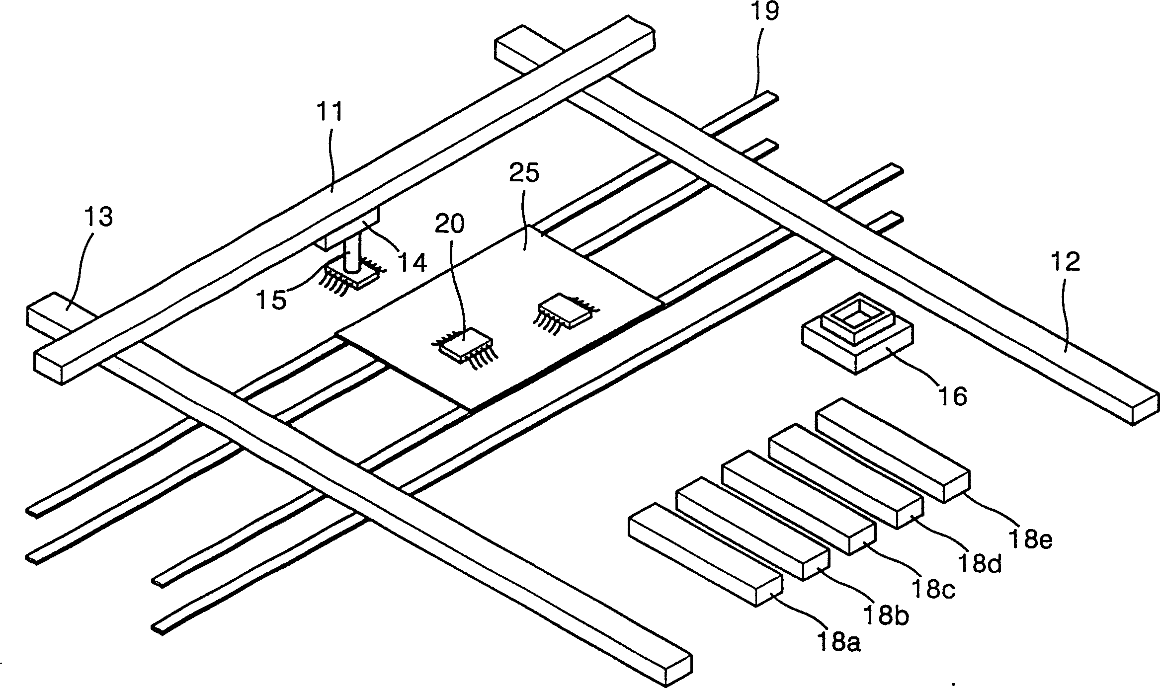
[0036] Figure 4A The structure of the component mounting apparatus which performs the component mounting method of this invention is shown. here, with figure 1 The same reference numerals denote the same parts with the same function. see Figure 4A , The component mounting device of the present invention includes: first and second Y-axes 12 and 13 installed parallel to each other; X-axis installed to be able to move along the first and second Y-axis 12 and 13; installed to be able to move along the X-axis 11 A moving suction head unit 14; a suction nozzle 15 mounted on the suction head unit 14 capable of rotating and moving up and down; a conveyor 19 for transferring a printed circuit board (PCB) 25 to a position where components are mounted. The suction head unit 14 moves between the component feeders 18a - 18e and the PCB 25 . The suction nozzle 15 moves up and down and rotates to hold the components and install the held components on the PCB 25 .

[0037] According to...


PUM


Abstract

Mounting parts is performed by recognizing a particular part feeder where a part to be mounted is contained among a plurality of part feeders, moving a head unit to a position for picking up a part on the part feeder, moving an image sensor, picking up a part from the particular part feeder with a suction nozzle installed at the head unit, moving the head unit to a position above the image sensor, detecting an image of the part held by the suction nozzle, moving the suction nozzle to a printed circuit board from the image sensor, and aligning the part with the printed circuit board while determining and compensating for an error generated when the part is picked up, and mounting the aligned part on the printed circuit board.

Description

technical field [0001] The present invention relates to a component mounting device, and a component mounting method, in particular to a component mounting device and a component mounting method, which can minimize and shorten the time and distance required for equipment to be moved for component mounting, and Can accurately identify the position of the part. Background technique [0002] Generally, electronic components such as semiconductor packages are mounted on printed circuit boards using component mounting devices. The component mounting apparatus picks up electronic components supplied from a component supply part such as a tray feeder or a tape feeder using vacuum suction and mounts the electronic components on a predetermined position on a printed circuit board. Here, the suction head unit moves the electronic component to the image sensor to obtain information about the posture of the component held by the suction nozzle. As the image sensor, a video camera (lin...

Claims


Application Information

Patent Timeline
Patent Type & Authority Patents(China)
IPC IPC(8): H05K13/04
CPCH05K13/0452H05K13/0813Y10T29/4913Y10T29/53191Y10T29/49131Y10T29/53178Y10T29/53087Y10T29/49133Y10T29/49004Y10T29/53052
Inventor 黄永洙赵泰衍申镇宇
Owner HANWHA TECHWIN CO LTD