Method for detecting the position of components placed on a substrate by pick-and-place robot

An identification method and automatic technology, applied in the direction of electrical components, electrical components, etc., can solve the problem that the substrate can no longer be used without considering the elimination of errors, and achieve the effect of saving time

Inactive Publication Date: 2006-01-18
ASM ASSEMBLY SYST GMBH & CO
View PDF3 Cites 0 Cited by
  • Summary
  • Abstract
  • Description
  • Claims
  • Application Information

AI Technical Summary

Problems solved by technology

In this case exclusion errors are generally no longer considered and the substrate is no longer usable

Method used


Image

  • Method for detecting the position of components placed on a substrate by pick-and-place robot
  • Method for detecting the position of components placed on a substrate by pick-and-place robot
  • Method for detecting the position of components placed on a substrate by pick-and-place robot

Examples


Embodiment Construction

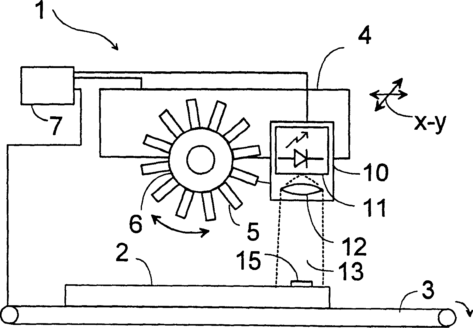
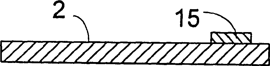
[0023] By means of the automatic inserting machine 1 shown in FIG. 1 and by means of a holder device 5 (such as a straw), the device 15 is taken out of a conveying unit not shown and positioned on the substrate 2 at a predetermined position. At this time, the substrate 2 is transferred on the automatic inserting machine by means of the transfer device 3. The support device 5 is fixed on the fixing device 6 on the inserting head 4 of the automatic inserting machine 1, and the inserting head-monitored by the control device 7-moves in the x-y-direction parallel to the substrate 2. Therefore, all positions of the substrate 2 can be reached. For example, a sensor 10 composed of an optical detector 11, an optical imaging device 12, and an image processing unit not shown, for example, which can be installed in a control device, acquires at least part of the inserted device 15 in its field of view 13. If the sensor 10 is fixed on the insertion head 4, its field of view 13 can reach every ...


PUM


Abstract

Position detection of components (15) placed on substrates (2) is so far effected visually outside the pick-and-place robot (1). Besides being a complicated process, when several components (15, 16) are placed on top of each other, the components (15) located in the bottom cannot be recognized. According to the inventive method, the position of the component (15) placed in the pick-and-place robot is detected by means of a sensor (10) located in the pick-and-place robot (1) shortly after the effective placing process has taken place. This makes it possible to timely detect errors and to easily adjust the positioning accuracy of the pick-and-place robot (1). A camera with a downstream image evaluation unit is used as sensor (10).

Description

Technical field [0001] The invention relates to a method for identifying the position of a device inserted on a substrate on an automatic insertion machine. Background technique [0002] When the SMD device (SMD = surface mount device) is automatically inserted on the substrate (such as a printed circuit board or a ceramic substrate), the individual device is taken out of the conveying device by means of an insertion head and then placed on the substrate in advance. Location positioning. [0003] A method is known from DE 41 21 404 in which a check is performed outside the automatic inserting machine after the inserting process to see whether all components have been positioned in a predetermined position. In addition, it is recommended there to correct the position or to supplement the insert. Because the installation position of the automatic inserting machine is not recognized, the inserted substrate must be sent to a separate device, which is too time-consuming in the manufac...

Claims


Application Information

Patent Timeline
Patent Type & Authority Patents(China)
IPC IPC(8): H05K13/08H05K13/04
CPCH05K13/08H05K13/0815
Inventor W·萨罗蒙J·普里特曼H·-H·格拉斯米勒
Owner ASM ASSEMBLY SYST GMBH & CO
Why Eureka
Try Eureka