Method and device for determining magnetic head position using boundary line detection method

A method of determining the boundary line, applied in the direction of the transducer head device, the configuration/installation of the recording head, the fixed installation, etc.

Inactive Publication Date: 2006-04-26
ALPS ALPINE CO LTD
View PDF0 Cites 0 Cited by
  • Summary
  • Abstract
  • Description
  • Claims
  • Application Information

AI Technical Summary

Problems solved by technology

[0015] However, the image obtained by camera photography cannot be analyzed at a distance shorter than the arrangement pitch of photodetection elements such as CCD, so when determining the edge of the slider on the magnetic head body 1, etc. The photodetection elements can be placed at a shorter pitch to determine the position

Method used


Image

  • Method and device for determining magnetic head position using boundary line detection method
  • Method and device for determining magnetic head position using boundary line detection method
  • Method and device for determining magnetic head position using boundary line detection method

Examples


Embodiment Construction

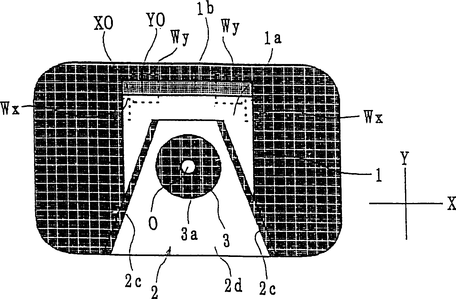
[0048] As described above, the boundary line detection method of the present invention can detect the boundary line between regions with different light reflection luminance with very high accuracy, so that the position of the boundary line can be determined with a size finer than the arrangement pitch of pixels. .

[0049] Furthermore, when the position determination of the magnetic head and the support member is carried out by this detection method, the position of the magnetic head main body can be determined with high precision, so that its flying distance can be stabilized.

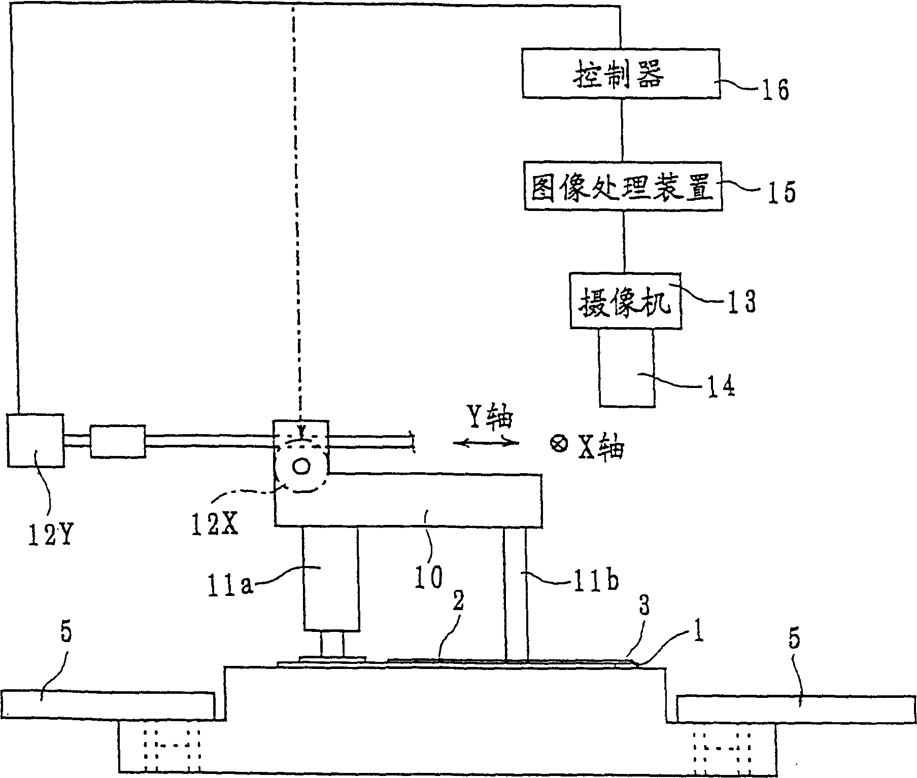
[0050] figure 1 It is a side view showing the magnetic head position specifying device of the present invention.

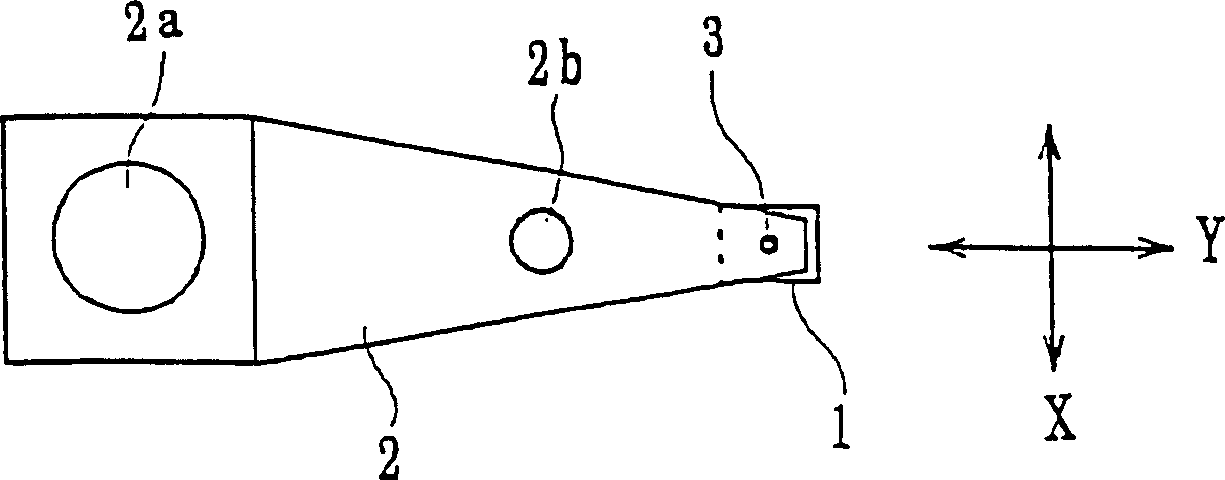
[0051] This head position determination device can be used for such as figure 2 A magnetic head device such as that used in a hard disk device is shown to implement position determination.

[0052] as figure 2 As shown, this magnetic head device is composed of a magnetic head main...


PUM


Abstract

A magnetic head position determination method and device using a boundary line detection method, the method comprising: applying light to a combined portion of a magnetic head body and a supporting member, and detecting a boundary line between regions having different light reflectances by using a camera equipped with a light detection element The detection method of the present invention is based on performing image processing on the detected amount of detected light, setting the area on the image where the luminance corresponding to the light detection element appears as a unit area, and comparing the luminance of the unit area arranged along a predetermined direction, To determine the position of the actual boundary line located in a unit area; by connecting the position of the determined boundary line between the unit areas, determine the arc of the pivot, and detect the center position of the circle according to the arc; press Adjust the relative position between the head body and the support member by adjusting the distance between the edge of the head body and the center point of the pivot obtained in the above steps within the allowable range; after the adjustment, fix the head body and the support member relative to each other.

Description

[0001] This application is a divisional application of Chinese invention patent application No. 98117118.4. technical field [0002] The present invention relates to a position determination method and a position determination device for position determination between a head main body used in a hard disk device and the like and a support member such as a carrier arm using a boundary line detection method. Background technique [0003] Figure 8A A plan view showing a conventional magnetic head position determination device, Figure 8B its side view. [0004] The magnetic head main body 1 is used in a hard disk device or the like, and is composed of a slider, a recording section and a reproducing section having a thin film structure provided at the trailing side end of the slider. The carrying arm 2, which is a supporting member supporting such a magnetic head main body 1, is composed of a leaf spring material. The head main body 1 is supported at the front end portion of t...

Claims


Application Information

Patent Timeline
Patent Type & Authority Patents(China)
IPC IPC(8): G06K9/46G11B5/53G11B5/49G06T1/00G06T7/00G11B5/55G11B21/08
CPCG11B5/55G11B21/083Y10T29/49027Y10T29/4903Y10T29/49032Y10T29/49036Y10T29/49131Y10T29/53261
Inventor 小泽利亮森山庄市相村浩
Owner ALPS ALPINE CO LTD
Why Eureka
Try Eureka