
Shuttle fiber laser

A fiber laser and shuttle technology, used in lasers, phonon exciters, laser parts, etc., can solve the problem of no flexible fiber replacement, and achieve the effect of improving conversion efficiency

Inactive Publication Date: 2006-05-17
SHANGHAI INST OF OPTICS & FINE MECHANICS CHINESE ACAD OF SCI
View PDF0 Cites 0 Cited by
  • Summary
  • Abstract
  • Description
  • Claims
  • Application Information

AI Technical Summary

Problems solved by technology

But there is no structure that can flexibly replace the optical fiber

Method used


Image

  • Shuttle fiber laser
  • Shuttle fiber laser
  • Shuttle fiber laser

Examples


Embodiment Construction

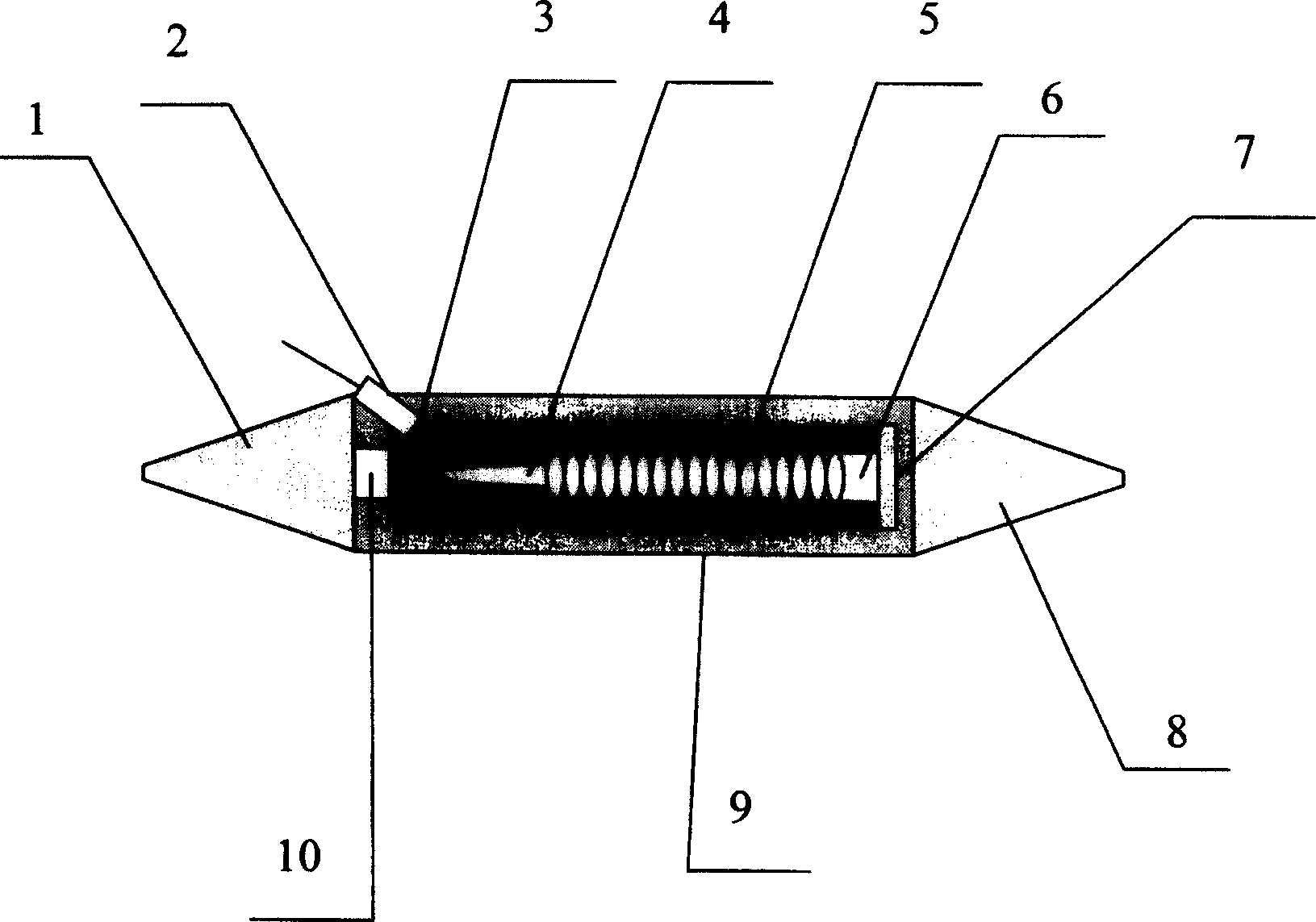
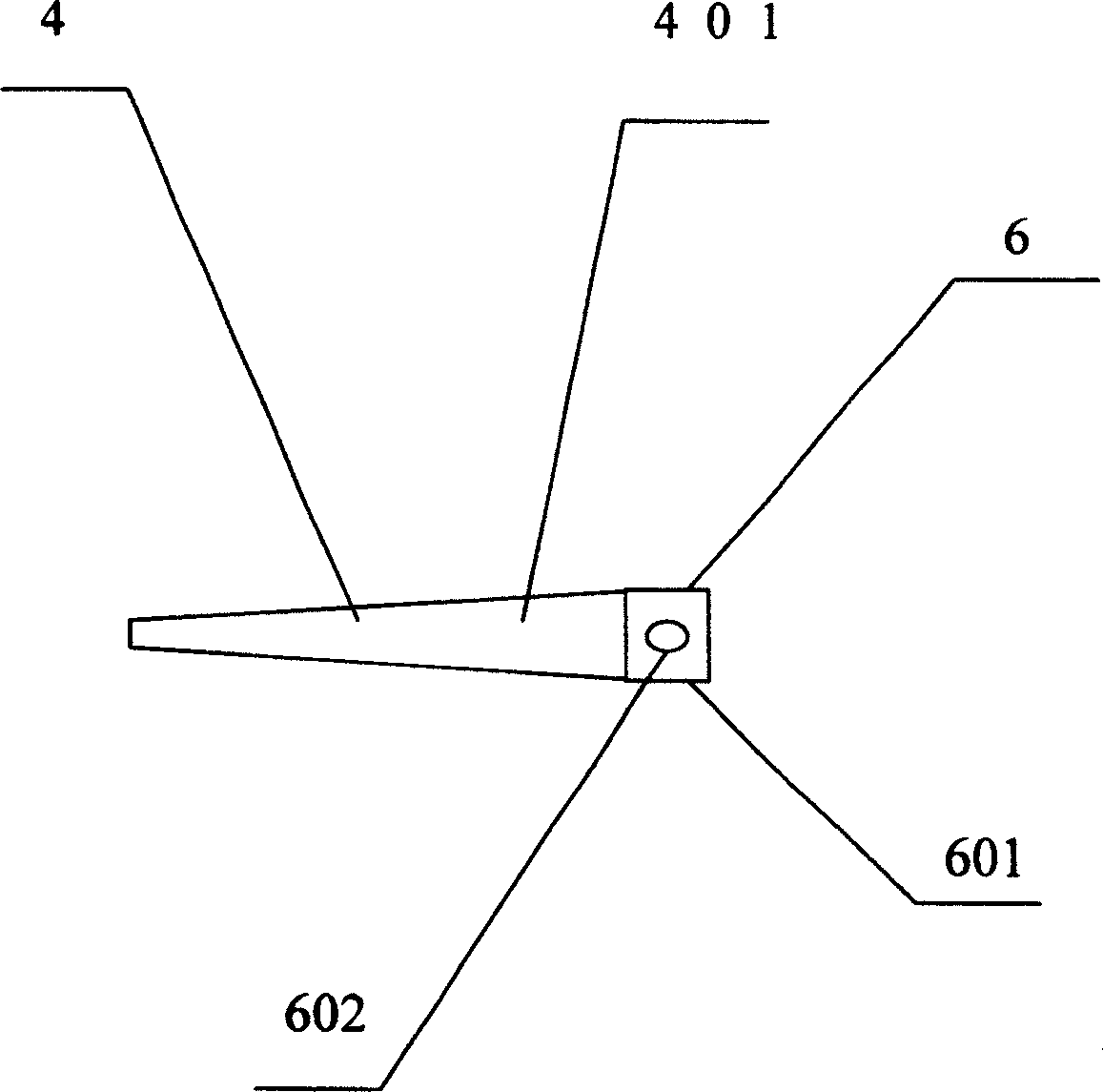
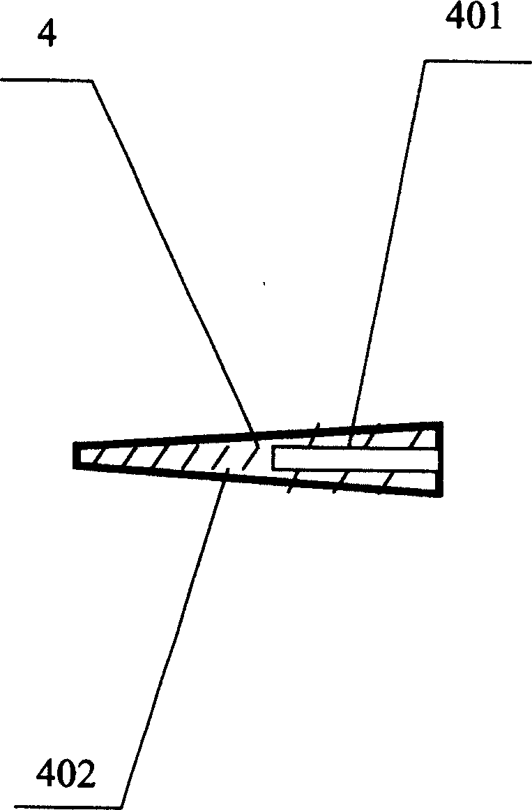
[0030] see first figure 1 , figure 1 It is a structural schematic diagram of the best embodiment of the shuttle fiber laser of the present invention. As can be seen from the figure, the shuttle fiber laser of the present invention includes, the most core element is an optical fiber 5, a weft tube pump source 4, and the fiber 5 is wound around the weft tube pump source 4, the weft tube pump source 4 is inserted on the support 603 of the weft tube pump source support 6, and the support 603 is fixed on the bracket support 601, and the weft tube pump source support 6 is supported by the weft in the weft tube support support 601. The tube bracket support hole 602 is passed through the weft tube base cross bar 701 and installed on the weft tube pump source base 7. The power supply 8 is the shuttle tip at the other end of the shuttle to directly provide energy for the weft tube pump source 4. The weft tube pump The source outer tube 402 and the weft tube pump source empty tube 401 c...


PUM


Abstract

A shuttle fiber laser, which includes a shuttle box, a shuttle tip and a shuttle-shaped power supply are separated at both ends of the shuttle box to form an integral shuttle-shaped structure, the shuttle box is provided with a weft tube pump source base, The bracket hole of a weft tube pump source bracket is sleeved on the crossbar of the weft tube pump source base, the weft tube pump source is fixed on the weft tube pump source bracket by using its hollow tube sleeve, and the core component optical fiber is wound On the outer wall of the weft tube pump source, the two ends of the optical fiber are inlaid with resonant cavity mirrors, the power supply directly provides energy for the weft tube pump source, the exit window is placed at the end of the shuttle box near the shuttle tip, the guide hook and the guide tube are placed On the side of the shuttle box near the tip of the shuttle. There is also a lens group for collimating light in the shuttle tip. The invention has the characteristics of flexible replacement of optical fibers and high pumping efficiency.

Description

Technical field: [0001] The invention relates to a fiber laser, in particular to a shuttle fiber laser. Background technique: [0002] In the prior art, "EMF SMPF-2030 Erbium-doped Micro Fiber Laser Module" (EMF Laser SMPF-2030 Ertium Micro Fiber Laser Module) developed by NP Optoelectronics Co., Ltd. is a kind of fiber extraction. But there is no structure that can flexibly replace the optical fiber. Invention content: [0003] The technical problem to be solved by the present invention is to overcome the deficiencies of the above-mentioned prior art, and provide a shuttle fiber laser with a flexible optical fiber structure and high pumping efficiency. [0004] Technical solution of the present invention is as follows: [0005] A shuttle fiber laser, which includes a shuttle box, a shuttle tip and a shuttle-shaped power supply are separated at both ends of the shuttle box to form an integral shuttle-shaped structure, the shuttle box is provided with a weft tube pump sou...

Claims


Application Information

Patent Timeline
Patent Type & Authority Patents(China)
IPC IPC(8): H01S3/067H01S3/00
Inventor 金石琦
Owner SHANGHAI INST OF OPTICS & FINE MECHANICS CHINESE ACAD OF SCI
Learn More