End-pumped high-power laser
An end-pump, laser technology, applied in lasers, laser parts, phonon exciters, etc., can solve problems such as incompatibility, and achieve the effect of improving absorption efficiency, high application value, and reducing thermal effects
- Summary
- Abstract
- Description
- Claims
- Application Information
AI Technical Summary
Problems solved by technology
Method used
Image
Examples
Embodiment 1
[0038] Example 1. Laser Diode End-Pumped Two-Mirror Cavity Laser
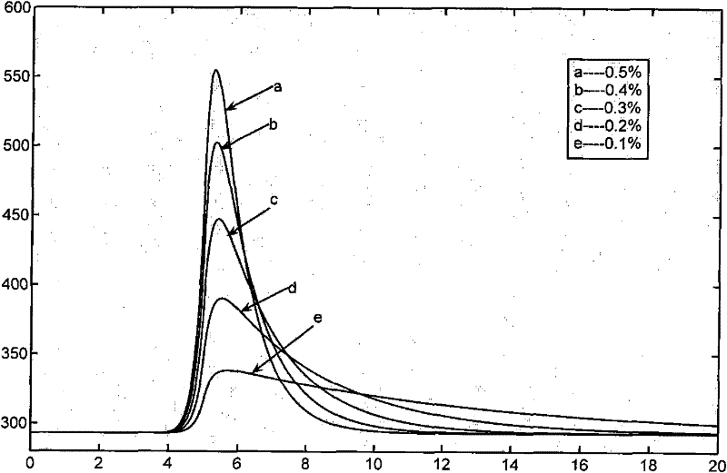
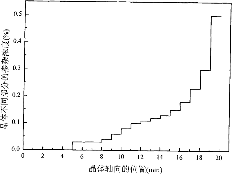
[0039] Such as Figure 5 As shown, it includes a pump source 11, a gain medium 12 and a laser resonator 13, and the gain medium 12 is gradedly doped Nd:YVO 4 Crystal, the crystal has a layered structure of 13 layers, the thickness of the first layer is 3 mm, the thickness of each layer of the last 12 layers is 1 mm, and the doping concentration of each layer is: 0.03%, 0.04%, 0.06%, 0.08%, 0.1% , 0.11%, 0.12%, 0.13%, 0.15%, 0.18%, 0.23%, 0.3%, 0.5%. The light emitted by the pump source 11 passes through the shaping and focusing system 14 to obtain a focused beam 15 , and the focused beam 15 is incident on the gain medium 12 placed in the resonant cavity 13 . The pump source 11 is a laser diode array or a fiber-coupled semiconductor laser, and the center wavelength of light emitted by the pump source 11 coincides with the absorption band of the gain medium 12 . The shaping focusing system is composed of two l...
Embodiment 2
[0040] Embodiment 2. Single-frequency laser with etalon mode selection
[0041] Such as Image 6 As shown, it includes a pump source 11, a gain medium 12, a laser cavity 13 and an etalon 21. The gain medium 12 is a gradedly doped Nd:YAG crystal, and the crystal is a 10-layer layered structure, each layer thickness 2 mm, the doping concentration of each layer is: 0.1%, 0.13%, 0.16%, 0.2%, 0.25%, 0.3%, 0.4%, 0.55%, 0.75%, 1%. The light emitted by the pump source 11 passes through the shaping and focusing system 14 to obtain a focused beam 15 , and the focused beam 15 is incident on the gain medium 12 placed in the resonant cavity 13 . The pump source 11 is a laser diode array or a fiber-coupled semiconductor laser, and the center wavelength of light emitted by the pump source 11 coincides with the absorption band of the gain medium 12 . The shaping focusing system is composed of two lenses, and its function is to shape the pump light into a beam satisfying the mode matching co...
Embodiment 3
[0042] Embodiment 3. Intra-cavity frequency-multiplied single-frequency laser with birefringent filter mode selection
[0043] Such as Figure 7 As shown, the light emitted by the pump source 11 passes through the shaping and focusing system 14 to obtain a focused beam 15, and the focused beam 15 is incident on the gain medium 12 placed in the resonant cavity 13, and the gain medium 12 is made of a gradually doped Nd:YAP crystal. , the crystal has a layered structure of 10 layers, the thickness of the first 5 layers is 1 mm each, and the thickness of the last five layers is 2 mm each, and the doping concentration of each layer is as follows: 0.1%, 0.13%, 0.16%, 0.2%, 0.25%, 0.3%, 0.4%, 0.55%, 0.75%, 1%. The pump source 11 is a laser diode array or a fiber-coupled semiconductor laser, and the center wavelength of light emitted by the pump source 11 coincides with the absorption band of the gain medium 12 . The shaping focusing system is composed of three lenses, and its funct...
PUM
 Abstract
Description
Claims
Application Information
 - R&D
- Intellectual Property
- Life Sciences
- Materials
- Tech Scout
- Unparalleled Data Quality
- Higher Quality Content
- 60% Fewer Hallucinations
Browse by: Latest US Patents, China's latest patents, Technical Efficacy Thesaurus, Application Domain, Technology Topic, Popular Technical Reports.
© 2025 PatSnap. All rights reserved.Legal|Privacy policy|Modern Slavery Act Transparency Statement|Sitemap|About US| Contact US: help@patsnap.com


