
Bearing stand

A bearing seat and bearing technology, applied in the direction of bearing components, shafts and bearings, pipeline laying and maintenance, etc., can solve problems such as hose damage

Inactive Publication Date: 2006-07-26
SMS DEMAG AG
View PDF0 Cites 0 Cited by
  • Summary
  • Abstract
  • Description
  • Claims
  • Application Information

AI Technical Summary

Problems solved by technology

[0003] Thus, there is a risk that the hose wears on the one hand as it rubs against the chocks, but mainly due to damage to the hose from occasional external shocks during roll changes during severe mill work, which may have been Get to where the hose is

Method used


Image

  • Bearing stand
  • Bearing stand

Examples


Embodiment Construction

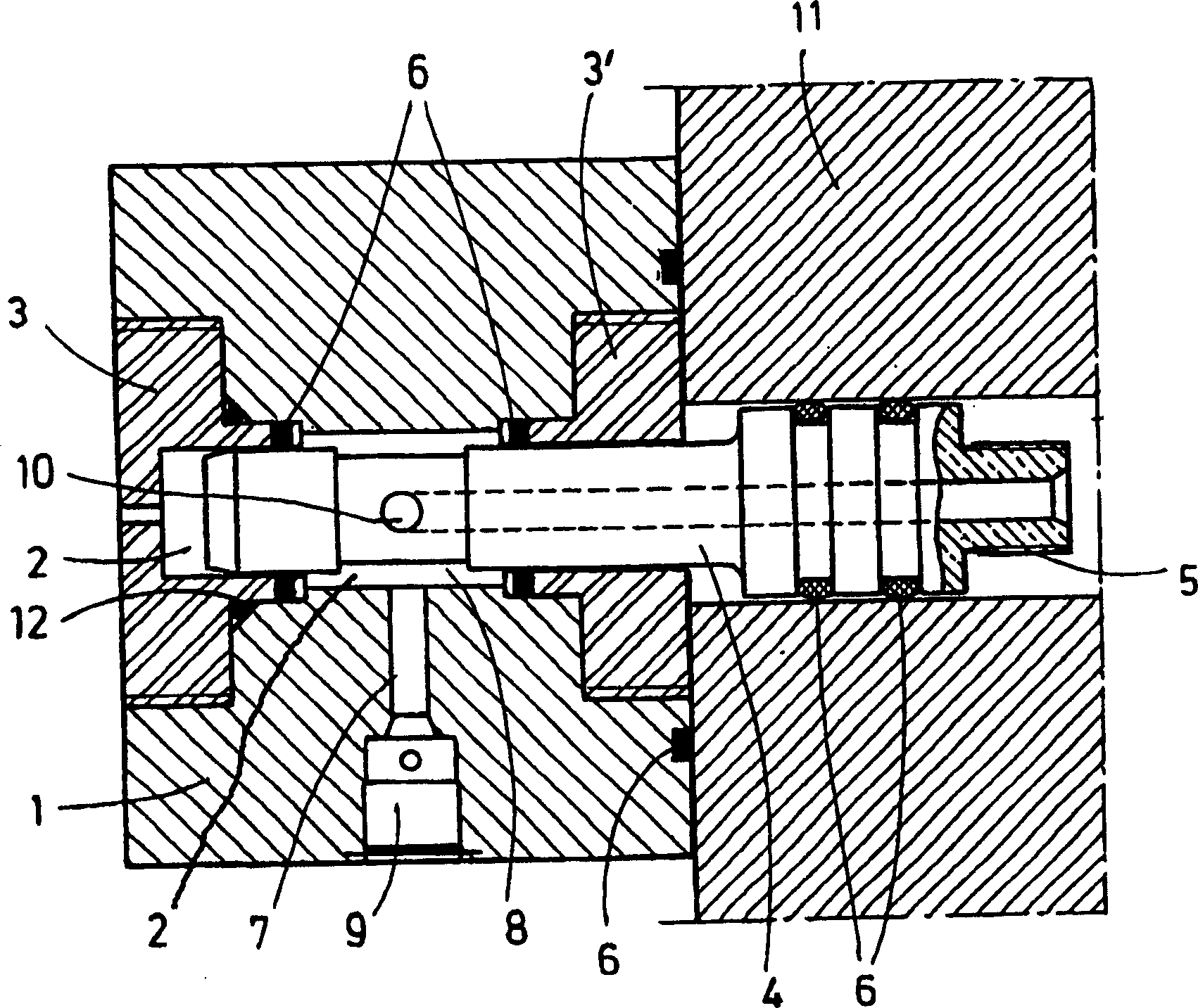
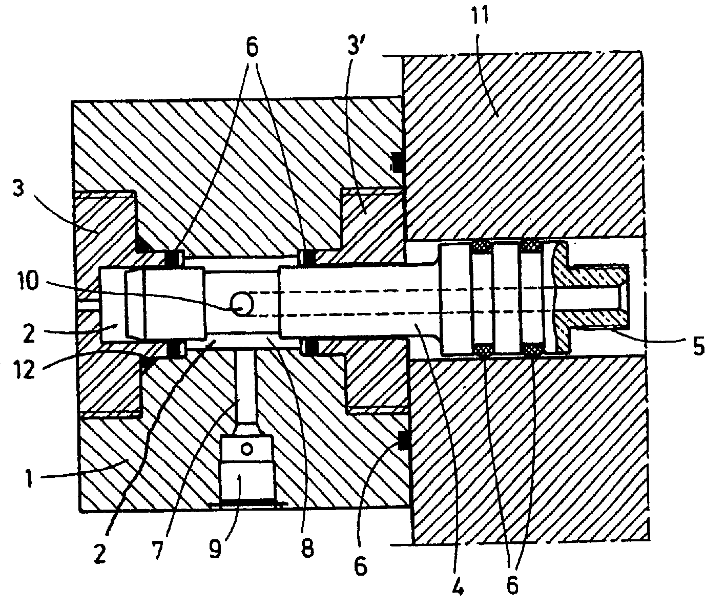
[0008] The figure shows a connection block 1 with a central hole 2 . Bearings 3 , 3 ′ are mounted in the central bore 2 and hold the connecting pipe 4 . The connecting pipe 4 is closed at one end and has a connection 5 at the open end for a line (not shown) or a hose (not shown). Here, the connection 5 and the hose connection connected to the connection 5 are supported in the bearing housing 11 on the connecting pipe 4 .

[0009] The connecting pipe 4 is sealed in the central bore 2 or in the bearings 3 , 3 ′ by a seal 6 . A radial bore 7 is provided in the connection block 1 and ends in an annular channel 8 . At the free end of the radial bore 7 there is a snap-action coupling 9 . The connecting pipe 4 has at least one radial opening 10 which communicates the annular channel 8 with the interior of the connecting pipe 4 .

[0010] Thus, hydraulic medium can be fed to the joint 5 of the connecting pipe 4 via the snap-action coupling 9 , the radial bore 7 , the annular chann...


PUM


Abstract

The invention relates to a connecting block (1) for the hydraulic supply lines of the hydrostatic unit of an oil-film bearing, which is fixed to a built-in bearing mounting (11) and retains at least one hydraulic hose, which is connected to the bearing bush that is displaceably located in the built-in bearing mounting (11). The aim of the invention is to improve a connecting block of this type in order to increase the operational reliability of the hydrostatic unit. To achieve this: the connecting block (1) comprises a bore (2), equipped with bearings (3, 3'), in which a connecting pipe (4) is mounted so that it can be displaced axially; the connecting block (1) has at least one second bore (7) that is positioned radially in relation to the central bore (2), the open end of said second bore being provided with a coupling (9) for a connecting hose; the radial bore (7) terminates in an annular channel (8) that surrounds the connecting pipe (4); the connecting pipe (4) has at least one radial opening (10) in the vicinity of the annular channel (8); one end of the connecting pipe (4) is closed; and a coupling (5) for a connecting hose that leads to the bearing bush is provided on the open end of the connecting pipe.

Description

technical field [0001] The invention relates to a bearing block on which a connection block for a hydraulic supply line of a hydrostatic device of an oil film bearing is fixedly arranged and holds a hydraulic hose connected to a bearing sleeve movably arranged in the bearing seat . Background technique [0002] Such a connecting block has a snap-action coupling, by means of which, for example during a roll change, the bearing housing can be connected to an oil supply line as quickly as possible. A hydraulic hose is also provided on the connection block, which can supply hydraulic oil to the bearing sleeve. These bearing sleeves are movably supported in the bearing housings, whereby the hydraulic hoses must compensate for movement between the bearing sleeves and the stationary connection block. For this purpose, the hose is attached openly to the bearing housing. [0003] Thus, there is a risk that the hose wears on the one hand as it rubs against the chocks, but mainly du...

Claims


Application Information

Patent Timeline
Patent Type & Authority Patents(China)
IPC IPC(8): F16L27/087F16L27/08F16L1/00
CPCF16L27/0812F16L27/087F16C33/10
Inventor R·许克K·凯勒
Owner SMS DEMAG AG
Learn More