
Experimental device for rotatable valve of engine

An experimental device and engine technology, applied in the direction of engine testing, measuring equipment, machine/structural component testing, etc., can solve problems such as deteriorating combustion, affecting intake air volume, singleness, etc., and achieve the effect of increasing vortex intensity

Active Publication Date: 2017-12-12
HEBEI UNIV OF TECH
View PDF12 Cites 2 Cited by
  • Summary
  • Abstract
  • Description
  • Claims
  • Application Information

AI Technical Summary

Problems solved by technology

But for a four-valve engine, due to the symmetrical arrangement of the double intake port structure and the two cam profiles driving the intake valves are almost the same, the two intake valves open to the same degree at the same time, so that the intake speed of the two intake valves and With the same intake air volume, the swirling airflow in the cross-sectional direction of the cylinder block cancels each other out, and the overall movement of the air in the cylinder shows a single longitudinal tumble flow mode, with almost no vortex flow, which is an important factor causing poor mixture formation and worsening combustion
If tangential air passage or rotating air passage is used to obtain vortex flow, the structure of the cylinder head will be complicated and the airflow resistance will increase.
When one intake valve is open and the other intake valve is closed, a large vortex can be generated (Wang Jian, Liu Dexin, Liu Shuliang, etc., Steady flow test research on the flow characteristics of the intake port of a four-valve gasoline engine[J]. Journal of Internal Combustion Engines, 2004, 22 (2): 182-186), using a sliding variable intake structure, setting valves in the intake manifold can also generate swirl and control swirl (Liu Ruilin, Liu Zengyong, Gao Jin, etc. Four-valve gasoline engine with variable oblique axis Experimental research on the in-cylinder vortex characteristics generated by the vortex system [J]. Internal Combustion Engine Engineering, 2006, 27(3): 29-32.), but it is equivalent to reducing or cutting off part of the intake passage, which affects the intake air volume

Method used


Image

  • Experimental device for rotatable valve of engine
  • Experimental device for rotatable valve of engine
  • Experimental device for rotatable valve of engine

Examples


Embodiment Construction

[0016] The present invention will be further described below in conjunction with the accompanying drawings and embodiments, but this should not be used as a limitation to the protection scope of the claims of the present application.

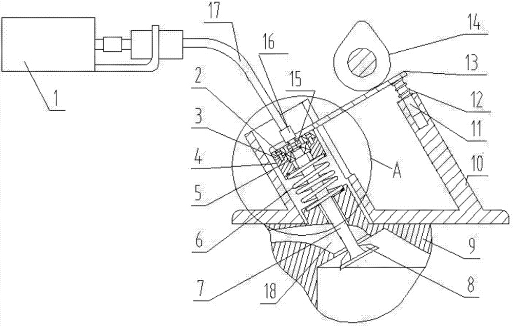
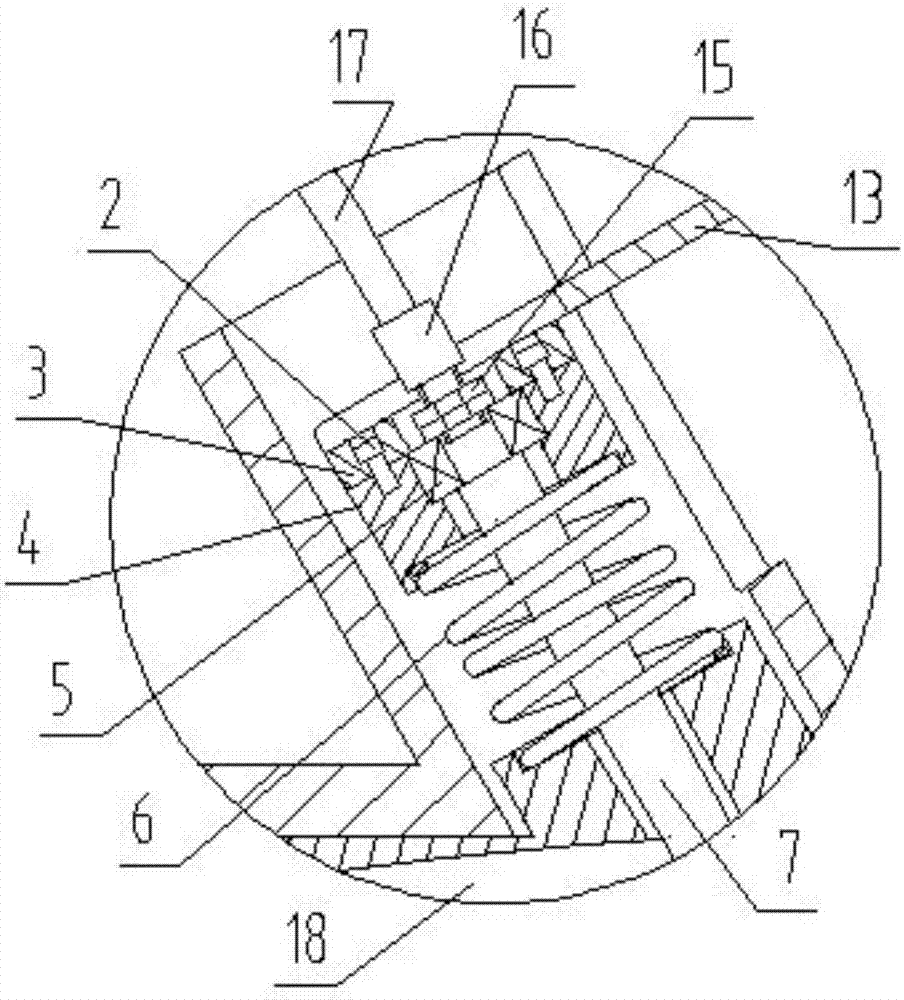
[0017] Engine swivel valve experimental device of the present invention (abbreviation device, see figure 1 and figure 2 ) includes speed regulating motor 1, bearing gland 3, bearing seat 4, bearing 5, hexagon socket bolt 2, lock nut 15, valve spring 6, valve with ridge 7, cylinder head 9, bracket 10, guide post 11, guide Column spring 12, pressure plate 13, intake cam 14, joint 16 and flexible shaft 17;

[0018] The output shaft of the speed-regulating motor 1 is connected to the flexible shaft 17, and the lower end of the flexible shaft 17 is connected to the tail of the valve 7 through the joint 16. When the speed-regulating motor 1 is started, the valve 7 can be driven to rotate; the tail of the valve 7 is equipped with a bearing 5, The be...


PUM


Abstract

The invention relates to an experimental device for a rotatable valve of an engine. The experimental device is characterized by comprising an adjustable-speed motor, a bearing gland, a bearing block, a bearing, an inner hexagonal bolt, a locking nut, a valve spring, a valve with back, a cylinder cover, a support, a guide pillar, a guide pillar spring, a press plate, an air inlet cam, a joint and a flexible shaft; an output shaft of the adjustable-speed motor is connected with the flexible shaft, the tail end of the lower part of the flexible shaft is connected with the tail part of the valve by virtue of the joint, and the adjustable-speed motor can drive the valve to rotate; the bearing is arranged at the tail part of the valve, the bearing gland compresses a bearing outer ring on the bearing block by virtue of the inner hexagonal bolt, a bearing inner ring is fastened at the tail part of the valve by virtue of the locking nut, the valve spring is embedded in a groove in the lower end of the bearing block, the lower end of the valve spring is embedded in a groove in the upper end of an extension part at the upper part of a simulated cylinder cover, and when the valve rotates, the bearing gland, the bearing block and the valve spring can not rotate respectively; a valve back structure is formed at the front end of the valve; the guide pillar is mounted below the right end of the pressing plate, and the guide pillar spring sheathes outside the guide pillar.

Description

technical field [0001] The invention belongs to the technical field of engines, and in particular relates to an engine swirling valve experimental device. Background technique [0002] For the engine, the presence of tumble and swirl at the same time is more conducive to the organization of the combustion process. But for a four-valve engine, due to the symmetrical arrangement of the double intake port structure and the two cam profiles driving the intake valves are almost the same, the two intake valves open to the same degree at the same time, so that the intake speed of the two intake valves and With the same intake air volume, the swirling airflow in the cross-sectional direction of the cylinder block cancels each other out, and the overall movement of the air in the cylinder shows a single longitudinal tumble flow mode, with almost no vortex flow, which is an important factor causing poor mixture formation and worsening combustion . If the vortex is obtained by using ...

Claims


Application Information

Patent Timeline
IPC IPC(8): G01M15/00
CPCG01M15/00Y02T10/12
Inventor 张士强李春书唐凤敏王一李俊阳
Owner HEBEI UNIV OF TECH
Learn More