Adjustment system with post-pressure of air compressor as control pressure

A technology for post-compressor pressure and regulation systems, which is applied to mechanical equipment, combustion engines, machines/engines, etc., and can solve the problem of complex structure of the booster system, which cannot take into account the low-speed and high-speed working conditions of the engine, exhaust Problems such as poor sealing of the piping system can achieve the effect of reducing the intake air flow, solving the sealing problem, and increasing the power

Inactive Publication Date: 2012-12-12
SHANGHAI JIAO TONG UNIV
View PDF7 Cites 5 Cited by
  • Summary
  • Abstract
  • Description
  • Claims
  • Application Information

AI Technical Summary

Problems solved by technology

However, the existing turbocharging systems cannot take into account the low-speed operating conditions and high-speed operating conditions of the engine well.
[0003] After searching the existing technical literature, it was found that Chinese patent number ZL200410050996.3, patent name: a variable modular pulse conversion supercharging device for a turbocharged diesel engine, the patented technology provides an exhaust device in the exhaust pipe The device with continuously variable volume can better take into account the high-speed and low-speed working conditions of the engine; but the change of the exhaust volume in the exhaust pipe is realized by moving the moving rod up and down, which requires an additional A special control mechanism is used to control the movement of the moving rod, so that the structure of the booster system becomes more complicated, and the sealing of the exhaust pipe system is also poor under high temperature conditions.

Method used


Image

  • Adjustment system with post-pressure of air compressor as control pressure
  • Adjustment system with post-pressure of air compressor as control pressure

Examples


Embodiment

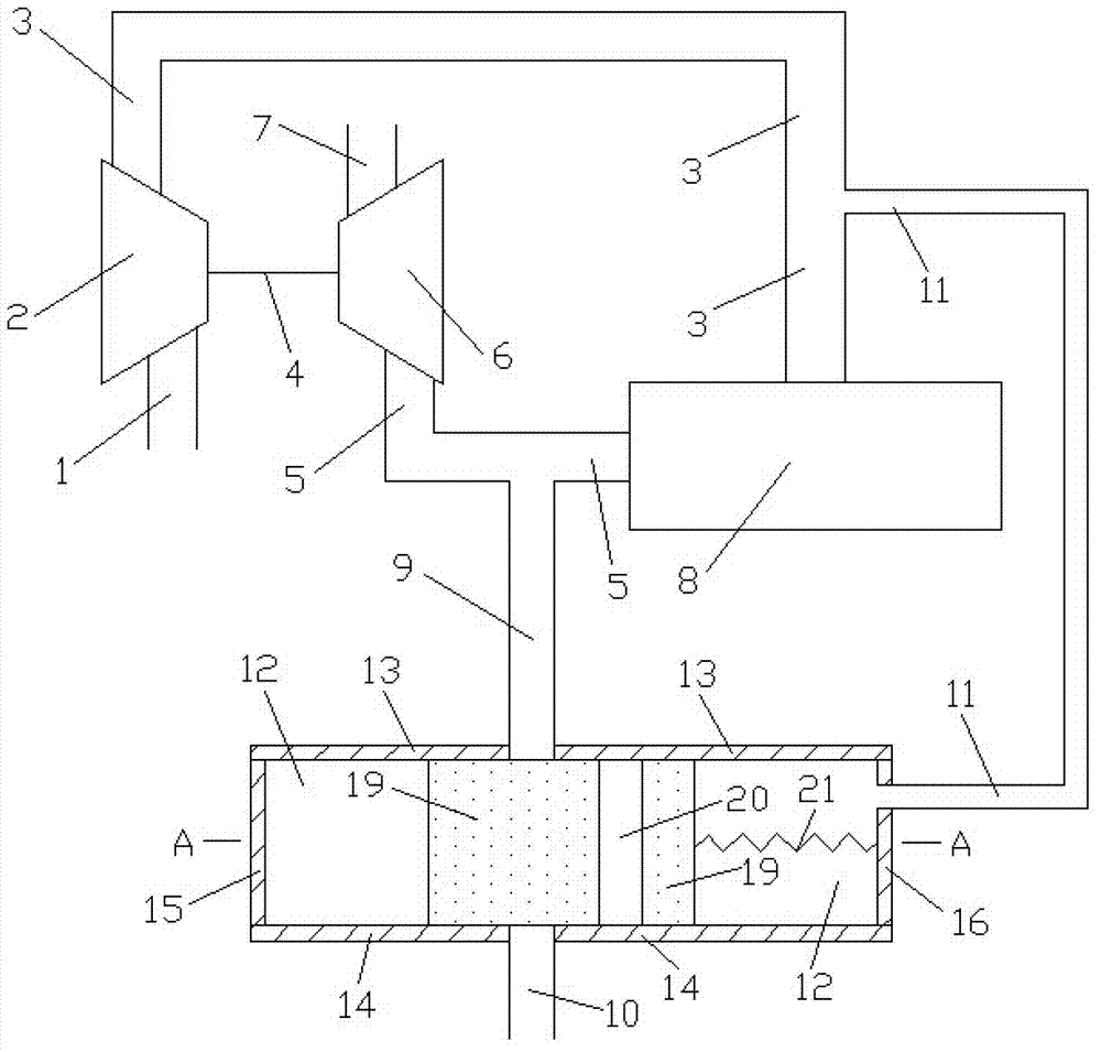
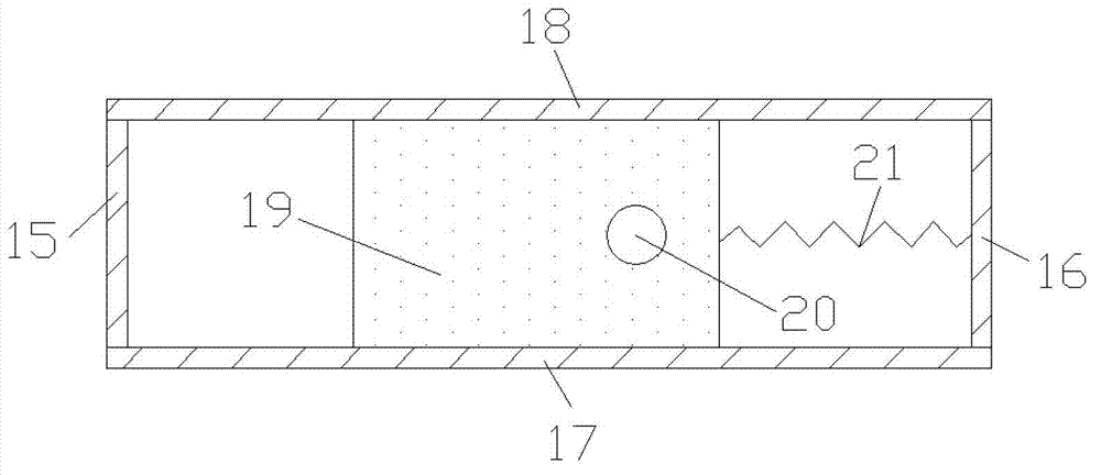
[0014] Such as figure 1 and figure 2 Shown, the present invention comprises: comprise compressor inlet pipe 1, compressor 2, engine inlet pipe 3, connecting shaft 4, engine exhaust pipe 5, turbine 6, turbine outlet pipe 7, engine 8, first connecting pipe 9, Second connecting pipe 10, third connecting pipe 11, volume cavity 12, volume cavity upper wall 13, volume cavity lower wall 14, volume cavity left wall 15, volume cavity right wall 16, volume cavity front wall 17, volume cavity rear wall 18. The moving body 19, the through pipe 20 and the elastic member 21, the compressor 2 and the turbine 6 are connected coaxially through the connecting shaft 4, the air inlet and outlet of the compressor 2 are respectively connected with the air outlet of the compressor inlet pipe 1 and the engine inlet pipe 3 The air inlet is connected, and the air inlet and outlet of the turbine 6 are connected with the air outlet of the engine exhaust pipe 5 and the air inlet of the turbine outlet pi...


PUM


Abstract

The invention provides an adjustment system with the post-pressure of an air compressor as control pressure in the technical field of an internal combustion engine, comprising an air compressor, a turbo, an engine, connection pipes, a volume chamber, a moving body, a penetration pipe and an elastic part, wherein two ends of the first connection pipe are communicated with an exhaust pipe and the upper wall face of the volume chamber respectively; two ends of the third connection pipe are communicated with the right wall face of the volume chamber and the air inlet pipe of the engine respectively; and the penetration pipe penetrates through the upper wall and the lower wall of the moving body. During the working process of the engine, the moving body can move left and right in the volume chamber; under the low speed working condition, since the pressure on the right side of the moving body is lower, the moving body moves rightward; the first connection pipe and the second connection pipe cannot be communicated; the air inflow of the engine is relatively increased; and the power rises. Under the high speed working condition, since the pressure on the right side of the moving body is higher, the moving body moves leftward; the first connection pipe and the second connection pipe are communicated with each other; the air input of the engine is relatively decreased; and the explosive pressure of each cylinder is decreased. The adjustment system with the post-pressure of the air compressor as the control pressure is rational in design, simple in structure and applicable for a turbo charging system of the engine.

Description

technical field [0001] The invention relates to an exhaust system in the field of internal combustion engines, in particular to an adjustment system in which the post pressure of a supercharged engine compressor is used as the control pressure. Background technique [0002] With the development of modern society, people have higher and higher requirements on the power and economy of the engine. In the case of a certain displacement, the most effective way to increase the output power of the engine is to provide more fuel for combustion. It is easy to provide more fuel to the cylinder through the injector, but it is not so easy to provide the amount of air to match the increased amount of fuel at the same time; The effect is poor. When the fuel injection volume is constant and the cylinder air intake volume is large, the combustion is better, and the fuel consumption and emissions are lower. The traditional naturally aspirated engine completely relies on the vacuum formed ...

Claims


Application Information

Patent Timeline
Patent Type & Authority Applications(China)
IPC IPC(8): F02B37/18
CPCY02T10/144Y02T10/12
Inventor 王俊席冒晓建唐航波
Owner SHANGHAI JIAO TONG UNIV
Why Eureka
Try Eureka