Compressed air heat-linkage energy-storage system based on reversible air engine

An air engine and compressed air technology, which is applied in the direction of non-variable engines, engine components, machines/engines, etc., can solve the problems of taking away large energy, reducing engine efficiency, and high residual pressure at the end of expansion, so as to improve the working ability , reduce energy loss, and quickly change working conditions

Inactive Publication Date: 2009-09-09
SHANDONG RONGQIANG ELECTRONICS TECH
View PDF0 Cites 14 Cited by
  • Summary
  • Abstract
  • Description
  • Claims
  • Application Information

AI Technical Summary

Problems solved by technology

After the fuel is burned, it contains a large amount of carbon dioxide and nitrogen oxides, which are discharged into the atmosphere and cause environmental pollution. Moreover, the unit is huge, the equipment is complicated, and the cost of miniaturization of the system is too high, so it is difficult to realize distributed energy storage.
[0005] Gas direct expansion power generation directly uses the energy generated by high-pressure gas when it is decompressed to generate electricity. The prime mover can have two forms, one is turbine type, and the other is piston type. The turbine type is similar to the gas turbine, and the high-pressure air cannot be obtained. Effective expansion, the discharged gas is still high-pressure gas, which will take away a lot of energy, and this waste will greatly reduce the comprehensive energy conversion rate
The piston prime mover is similar to the internal combustion engine, but in the current technical scheme, the residual pressure at the end of the piston engine’s intake stroke expansion is relatively high, and a large amount of energy is released by the subsequent exhaust stroke without being fully utilized. Inevitable reduction in eff

Method used


Image

  • Compressed air heat-linkage energy-storage system based on reversible air engine
  • Compressed air heat-linkage energy-storage system based on reversible air engine
  • Compressed air heat-linkage energy-storage system based on reversible air engine

Examples


Embodiment Construction

[0043] The present invention will be further described below in conjunction with the accompanying drawings and embodiments.

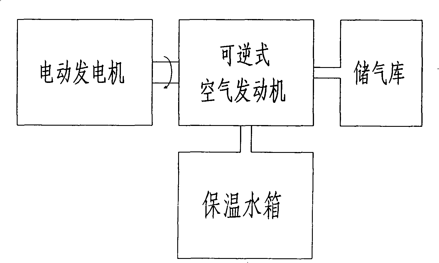
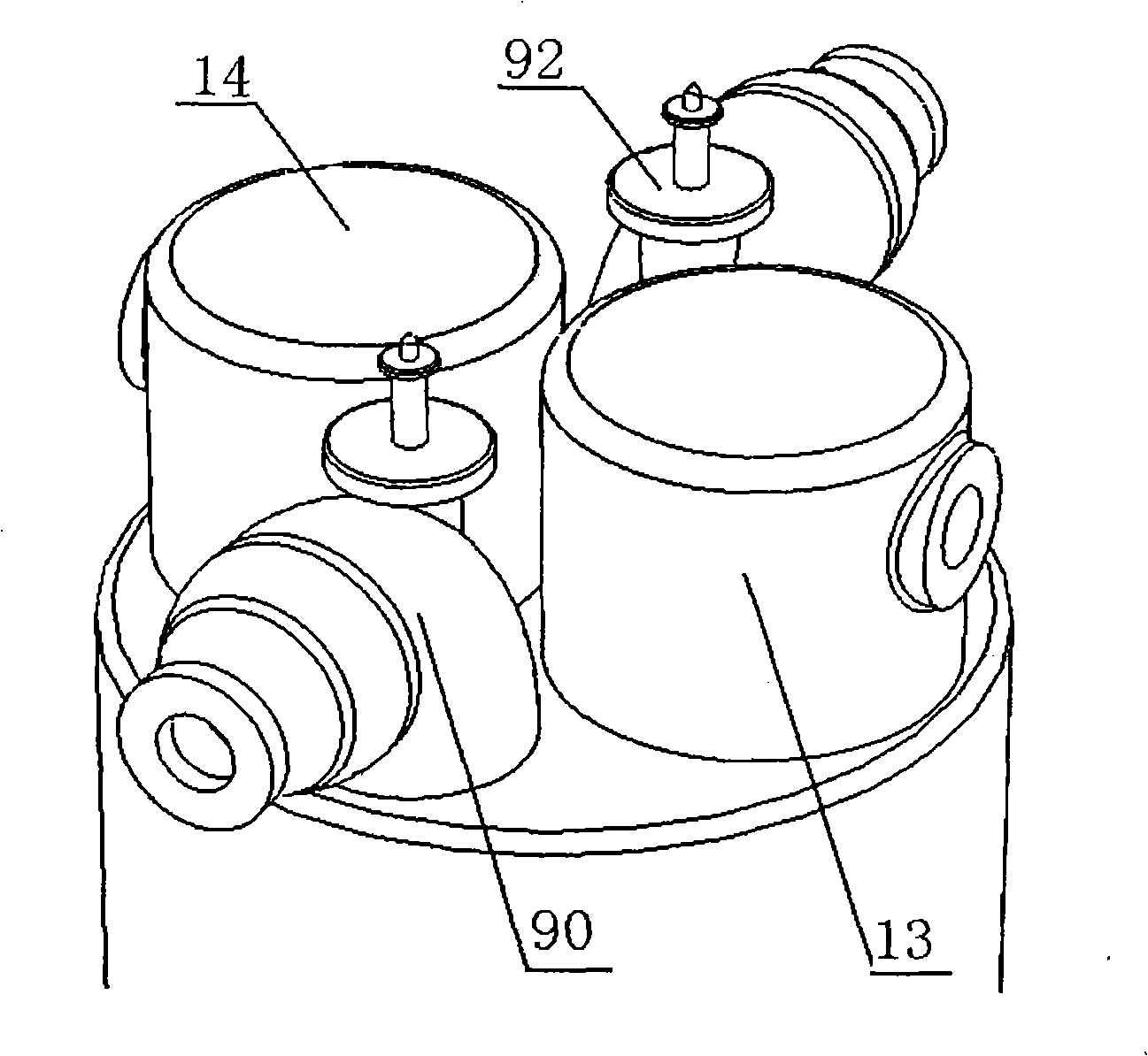
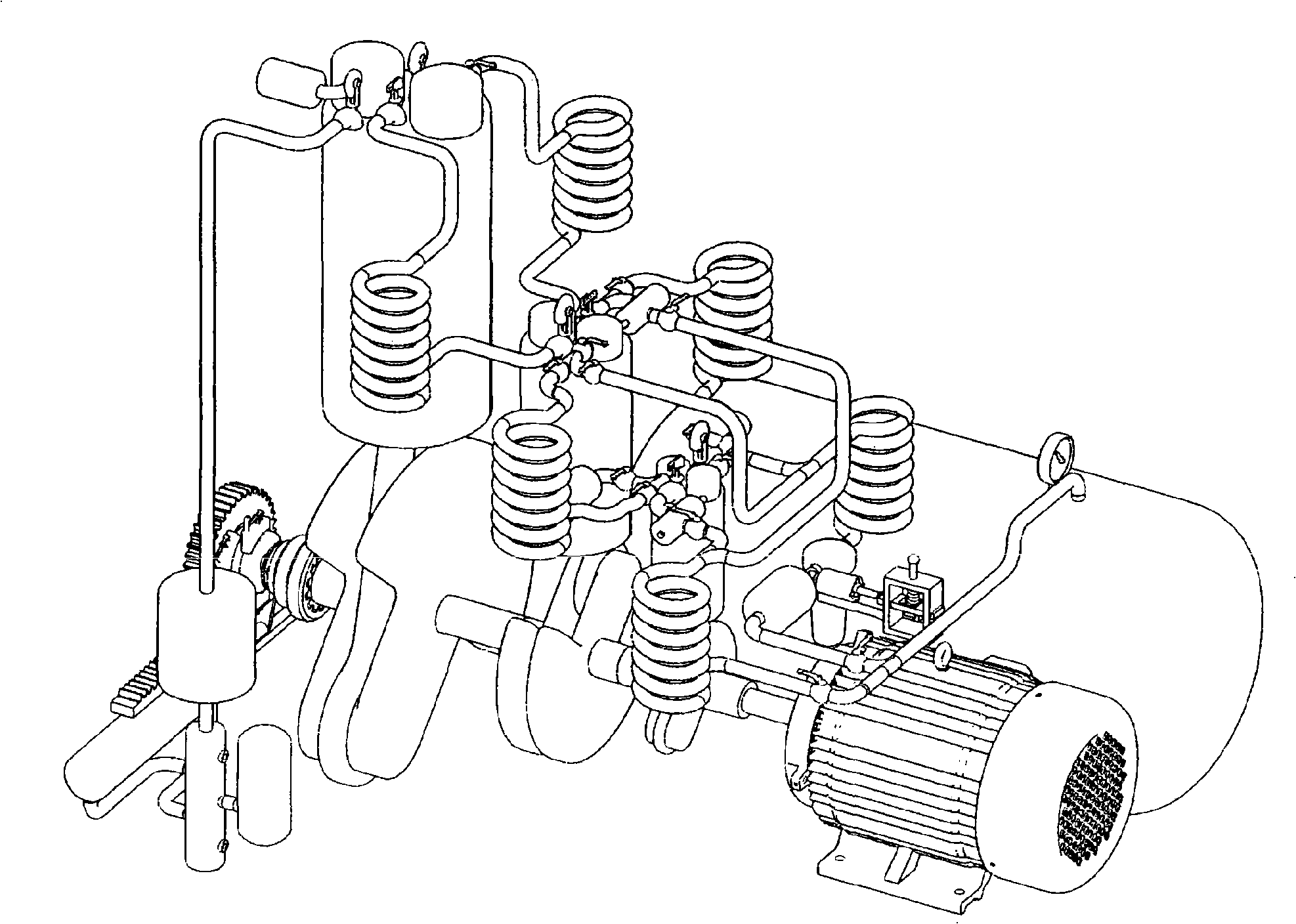
[0044] Such as figure 1 - As shown in FIG. 8 , the overall structure of the present invention includes four parts: a motor generator 1 , a reversible air engine, an air storage 24 and an insulated water tank 23 . The motor generator 1 is connected to the reversible air engine through the speed reducer 2, the reversible air engine is connected to the gas storage 24 through pipelines, and the heat preservation water tank 23 is connected to the cooler, regenerator and water jacket of the reversible air engine; the gas storage 24 is provided with pressure gauge 25.

[0045] The motor generator 1 is a generator that doubles as a motor or a motor that doubles as a generator, or a squirrel cage induction motor or a synchronous motor, or a reversible motor generator in a pumped storage power station.

[0046] The gas storage 24 is a cave or a salt rock layer ...


PUM


Abstract

The invention relates to a compressed air heat-linkage energy-storage system based on a reversible air engine, which comprises a motor generator, the reversible air engine, an air reservoir and an heat insulation water tank, wherein the motor generator is connected with the reversible air engine by a speed reducer, and the reversible air engine is respectively connected with the air reservoir and the heat insulation water tank. At the valley period of power consumption, compressed air is made and stored in the air reservoir, and the released heat is stored in the water; at the peak period of power consumption, the compressed air is utilized to drive the reversible air engine to generate electricity, and the stored heat water is used for heating the compressed air. The reversible air engine integrates a compressor and an engine into a whole body, adopts the technical schemes of tail gas pressure stabilization and timely cylinder variable, eliminates the energy loss taken away by tail gas and the decompression energy loss during the gas inlet and has high energy conversion efficiency. The system can be used for peak clipping and valley filling and emergency standby of an electric power system and also solve the intermittent bottleneck of wind power generation as well as the development and the utilization of the off-peak electrical power at night.

Description

technical field [0001] The invention relates to an electric energy storage system, in particular to a compressed air thermal energy storage system based on a reversible air engine. Background technique [0002] Unbalanced power system load is a major scientific research topic in the world today. As a product, electric energy has particularity. The biggest feature is that it cannot be stored, and is affected by the relationship between supply and demand and the change of supply and demand structure in the electricity market. Therefore, electric energy fluctuates frequently and in a large range. , There is a large peak and valley period in daily electricity consumption. With the continuous growth of my country's electricity demand, the gap between peak and valley loads is constantly widening, and the imbalance in power grid operation is increasing, and the growth rate of the peak-valley difference is greater than the growth rate of the load. The limitation of power supply and...

Claims


Application Information

Patent Timeline
IPC IPC(8): F02C6/14F03G7/00F01D1/06F01D25/00F01B29/10F01B23/00F01L1/00F01L1/04
Inventor 武睿张琪
Owner SHANDONG RONGQIANG ELECTRONICS TECH
Why Eureka
Try Eureka