Lateral structure and arranging method of steam turbine generator unit of 1000MW-grade set in thermal power plant

A technology for steam turbine generator sets and thermal power plants, which is applied to steam engine installations, machines/engines, and mechanical equipment, etc., can solve the problems of long length of steam and water pipelines, high requirements for construction organization, and large engineering cost, and achieves simple construction organization, Reduce pressure drop and heat dissipation loss, improve the effect of working performance

Active Publication Date: 2012-02-15
NORTHWEST ELECTRIC POWER DESIGN INST OF CHINA POWER ENG CONSULTING GROUP
View PDF5 Cites 13 Cited by
  • Summary
  • Abstract
  • Description
  • Claims
  • Application Information

AI Technical Summary

Problems solved by technology

[0002] In the thermal power plants currently under construction and put into operation in China with a single unit capacity of 1000MW, most of the main plant layout adopts the traditional four-column layout (that is, the turbine room, deaerator room, coal bunker room, boiler room) layout plan (a few units use The layout scheme of the side coal bunker was adopted), in which the turbo-generator sets are arranged in a longitudinal row, that is, the longitudinal axis of the turbo-generator set is parallel to the longitudinal axis of the turbine room (the direction from the turbine room to the turbine room is called the longitudinal direction, and the direction along the turbine room The direction to the boiler room is referred to as the horizontal direction); when the steam turbine generator set is arranged in a longitudinal row, the span of the steam turbine room is small, but the longitudinal length is relatively large. In order to align the center of the boiler with the center of the steam turbine generator set, the The distance is large, the volume of the main workshop is large, the length of the steam-water pipeline is long, and the project cost is relatively high; in addition, according to the characteristics of the longitudinal arrangement of the steam turbine generator set, the generator stator of one unit is located far away from the maintenance site. After hoisting, the translation needs to pass through areas such as the high-pressure cylinder of the steam turbine, which requires high construction organization

Method used


Image

  • Lateral structure and arranging method of steam turbine generator unit of 1000MW-grade set in thermal power plant
  • Lateral structure and arranging method of steam turbine generator unit of 1000MW-grade set in thermal power plant
  • Lateral structure and arranging method of steam turbine generator unit of 1000MW-grade set in thermal power plant

Examples


Embodiment Construction

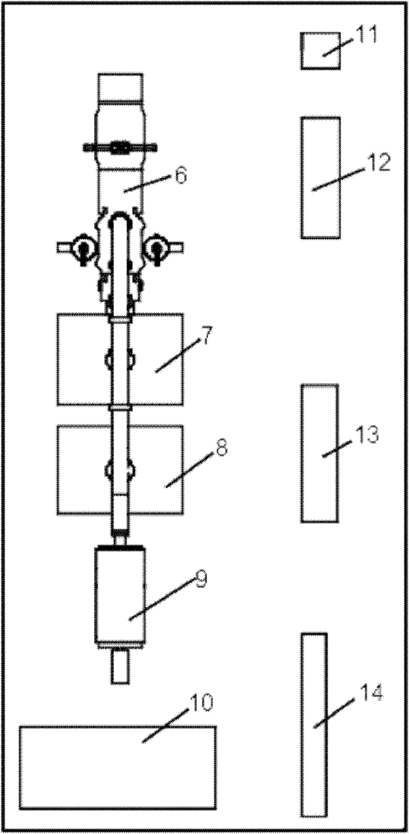
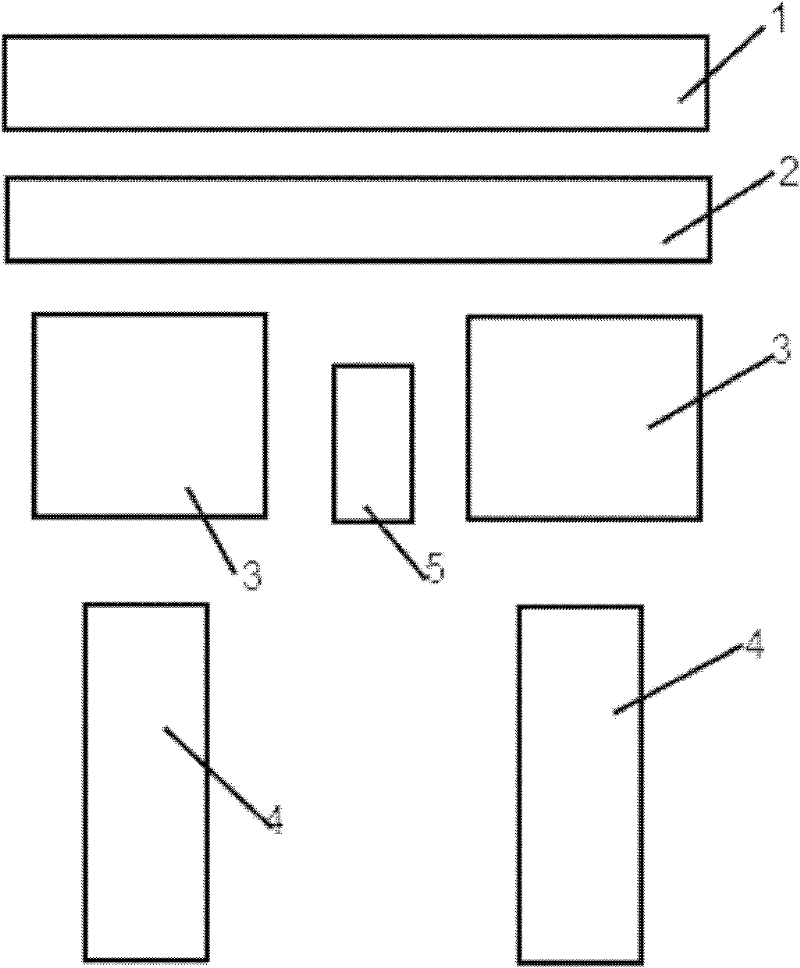
[0022] The present invention is described in further detail below in conjunction with accompanying drawing:

[0023] Such as figure 1 As shown, the main workshop adopts the layout scheme of turbine room and boiler room, and the 7m wide furnace front low seal is arranged between the turbine room and the boiler room. The coal bunker adopts the side coal bunker scheme and is arranged between the two boilers. The horizontal arrangement is adopted, the center line of the steam turbine generator set is aligned with the center line of the boiler room and the head of the steam turbine is arranged facing the boiler room, and the oxygen removal room is arranged on the left side of the steam turbine generator set (viewed from the direction of the head of the steam turbine). The site is set at the tail of the generator to facilitate the organization of construction, and a centralized control building is arranged between the two generators. The turbine room and the deaeration room are div...


PUM


Abstract

The invention discloses a lateral structure and arranging method of a steam turbine generator unit of a 1000MW-grade unit in a thermal power plant. A bunker bay is arranged between two boiler houses or between a boiler house and a steam turbine house; the longitudinal axis of the steam turbine generator unit is vertical to that of the steam turbine house, and the head of a steam turbine in the steam turbine house faces to the boiler house; and the central line of the steam turbine generator unit is aligned to the central line of a boiler. The invention has the advantages that: (a) the volume of a main power house is reduced; (b) the length of a steam-water pipeline is reduced, and particularly, the length of an expensive high-temperature and high-pressure steam pipeline in a steam pipeline system and the pressure reduction and heat radiation loss of the pipeline system are reduced; (c) no restriction of generator arrival time exists during field construction and the construction organization is simple; and (4) the tail of a generator of each unit is provided with an independent overhaul field.

Description

Technical field: [0001] The invention belongs to the field of construction, and relates to a 1000MW class unit steam turbine generator set in a thermal power plant, in particular to a method for horizontally arranging a 1000MW class unit steam turbine generator unit. Background technique: [0002] In the thermal power plants currently under construction and put into operation in China with a single unit capacity of 1000MW, most of the main plant layout adopts the traditional four-column layout (that is, the turbine room, deaerator room, coal bunker room, boiler room) layout plan (a few units use The layout scheme of the side coal bunker was adopted), in which the turbo-generator sets are arranged in a longitudinal row, that is, the longitudinal axis of the turbo-generator set is parallel to the longitudinal axis of the turbine room (the direction from the turbine room to the turbine room is called the longitudinal direction, and the direction along the turbine room The direc...

Claims


Application Information

Patent Timeline
Patent Type & Authority Applications(China)
IPC IPC(8): E04H5/02E04G21/14F01K13/00
Inventor 朱军程政马晓峰马欣强宋江文崔凯平张方绮曹嘉李素娟
Owner NORTHWEST ELECTRIC POWER DESIGN INST OF CHINA POWER ENG CONSULTING GROUP
Why Eureka
Try Eureka