Injection/drainage air-supply turbocharging system

A technology of turbocharger system and turbocharger, which is applied in the direction of machine/engine, internal combustion piston engine, mechanical equipment, etc., can solve the problems of unstable work, limited promotion and application, consumption of large high-pressure air, etc., and saves money The effect of usage

Inactive Publication Date: 2011-07-20
孙敏超 +1
View PDF9 Cites 14 Cited by
  • Summary
  • Abstract
  • Description
  • Claims
  • Application Information

AI Technical Summary

Problems solved by technology

Therefore, although the prior art scheme can rely on the short-time ejection air supply (the consumed jet flow air supply high-pressure air quantity is not large), the transient characteristics (acceleration) of the internal combustion engine can be effectively improved, but if the air supply is to be maintained If the resulting high supercharging pressure remains unchanged for a long time, it must be continuously injected with high-pressure air for a long time to replenish the air, thereby consuming a large amount of high-pressure air. This shortcoming obviously limits the use of existing technical solutions. Promotion and application to improve performance in low working conditions
[0006] 2) Using the existing high-pressure air ejection air replenishment scheme, since the boost pressure generated by the compressor of the turbocharger will suddenly increase sharply during the air replenishment, it often causes the surge of the compressor, making the compressor Generates strong vibration and airflow fluctuations and cannot work stably

Method used


Image

  • Injection/drainage air-supply turbocharging system
  • Injection/drainage air-supply turbocharging system
  • Injection/drainage air-supply turbocharging system

Examples


Embodiment Construction

[0029] Hereinafter, the technical content of the present invention will be further described through the embodiments and in conjunction with the accompanying drawings.

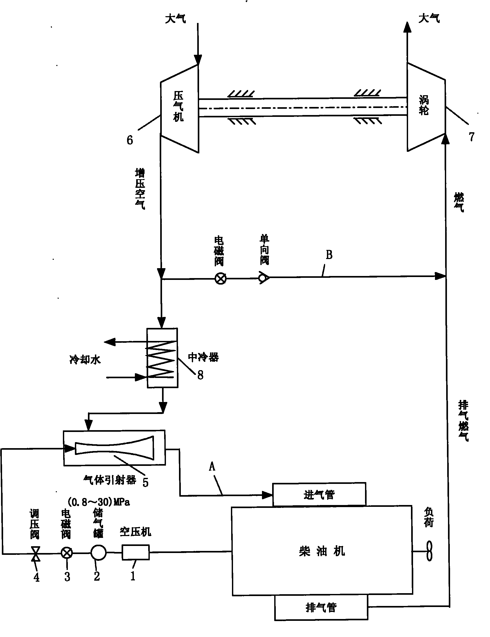
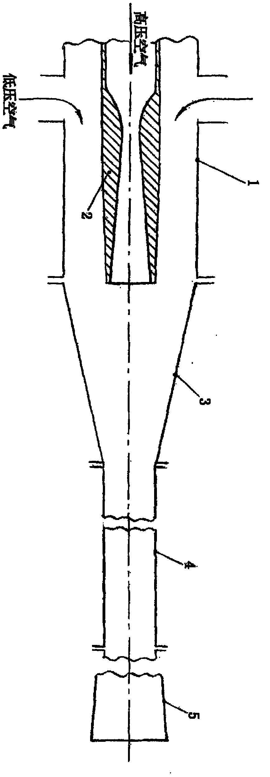
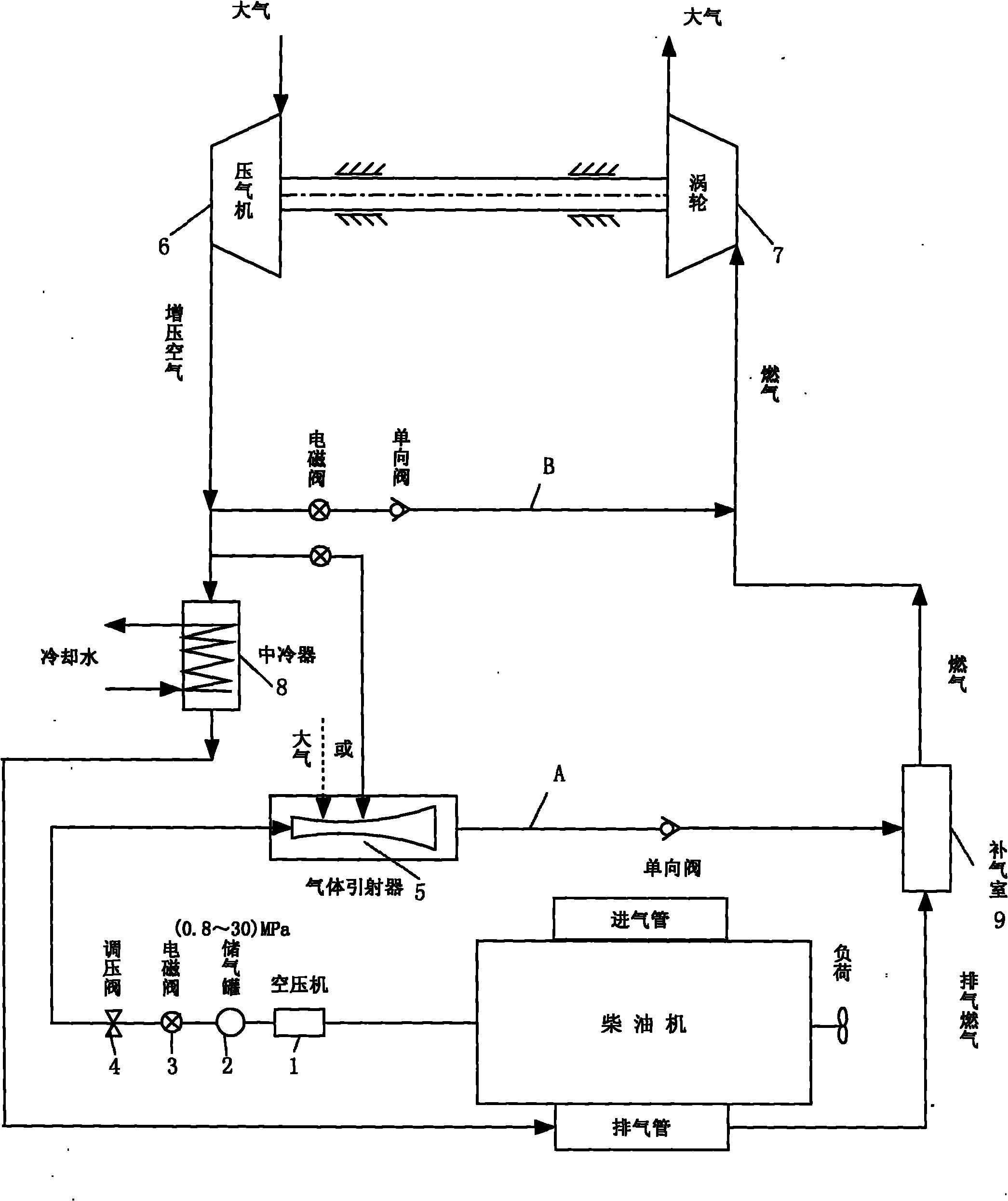
[0030] As mentioned above, the technical core of the present invention is to use the high-pressure compressed air flowing out from the air storage tank of the high-pressure compressed air supply device to accelerate the high-speed jet air formed by its expansion in the nozzle pipe of the gas injector to inject The low-pressure charge air that flows into the gas ejector cylinder from the outlet of the intercooler or the ambient air or the compressor outlet of the turbocharger is bypassed, and the two are mixed in the mixing section of the ejector and boosted through the diffuser tube Afterwards, "complement air" is formed, which is introduced into the intake pipe of the internal combustion engine and / or the guide tube installed in the box-shaped supplementary air chamber between the outlet flange of the exhaust ...


PUM


Abstract

The invention discloses an injection / drainage air-supply turbocharging system which is applied to a turbocharged internal combustion engine of vehicles, ships and engineering machines to improve the low (rotating speed and load) working condition performance and the transient characteristics of the turbocharged internal combustion engine. Through two supplementary air supply structures, namely a high pressure air injection air supply pipeline and a turbocharged air drainage air supply pipeline of the system, charging air flowing into the internal combustion engine and combustion air flowing into a turbine are supplied, so that the power and the turbocharging pressure of the turbine are greatly increased, and the fuel consumption, the exhaust temperature and the harmful emission are obviously reduced. Compared with the prior art, the invention has the advantages of mature technology, simple structure, safe and reliable use, great conditioning degree and good effect.

Description

technical field [0001] The invention relates to a turbocharger system in the technical field of internal combustion engine supercharging for vehicles, ships and engineering machinery. Background technique [0002] The current situation and future development trend of modern internal combustion engines continuously increasing the power density per liter makes the average effective pressure of internal combustion engines and the supercharging ratio of turbochargers higher and higher. Since the internal combustion engine turbocharging system is the joint operation between the turbocharger of the rotary impeller machine and the internal combustion engine of the reciprocating piston machine, at this time, the contradictions between the two machines due to the different flow characteristics of each other are not suitable for each other. It is more prominent and serious. Among them, the problem of how to improve the performance and transient characteristics (acceleration) of the h...

Claims


Application Information

Patent Timeline
Patent Type & Authority Applications(China)
IPC IPC(8): F02B37/04F02B37/12F02B37/16F02B29/04
CPCY02T10/146Y02T10/144Y02T10/12
Inventor 孙敏超孙正柱
Owner 孙敏超
Why Eureka
Try Eureka