Supercharge Your Innovation With Domain-Expert AI Agents!

Knob for fixing instrument baseplate

一种旋钮、仪器的技术,应用在仪器的零部件、仪器、支承机器等方向,能够解决旋钮无法再转动、仪器底板不能被正确固定等问题

Inactive Publication Date: 2006-08-02
PHILIP VOGT
View PDF1 Cites 0 Cited by
  • Summary
  • Abstract
  • Description
  • Claims
  • Application Information

AI Technical Summary

Problems solved by technology

As a result, the screw housing 1 and the chuck 6 are locked to each other, to be precise, so that the knob cannot be turned any further
As a result, the knob had to be replaced entirely
In addition, the fastening effect on the instrument base can be adversely affected thereby, so that the instrument base is locked or cannot be fixed correctly

Method used


Image

  • Knob for fixing instrument baseplate
  • Knob for fixing instrument baseplate
  • Knob for fixing instrument baseplate

Examples


Embodiment Construction

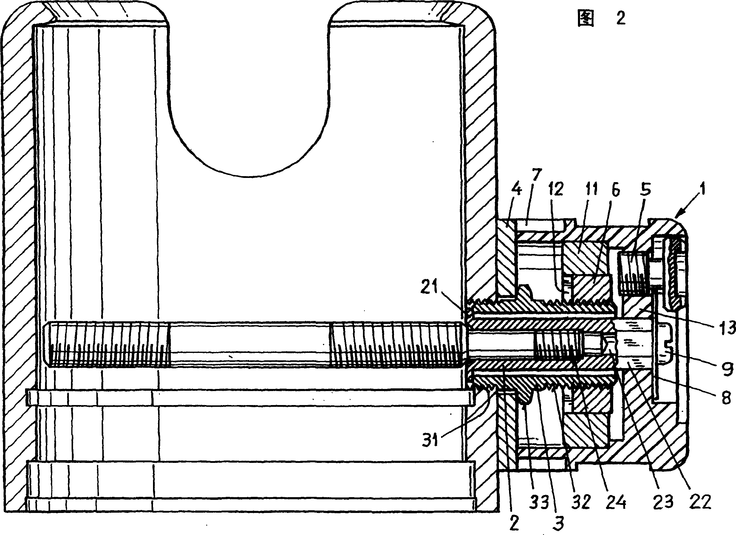
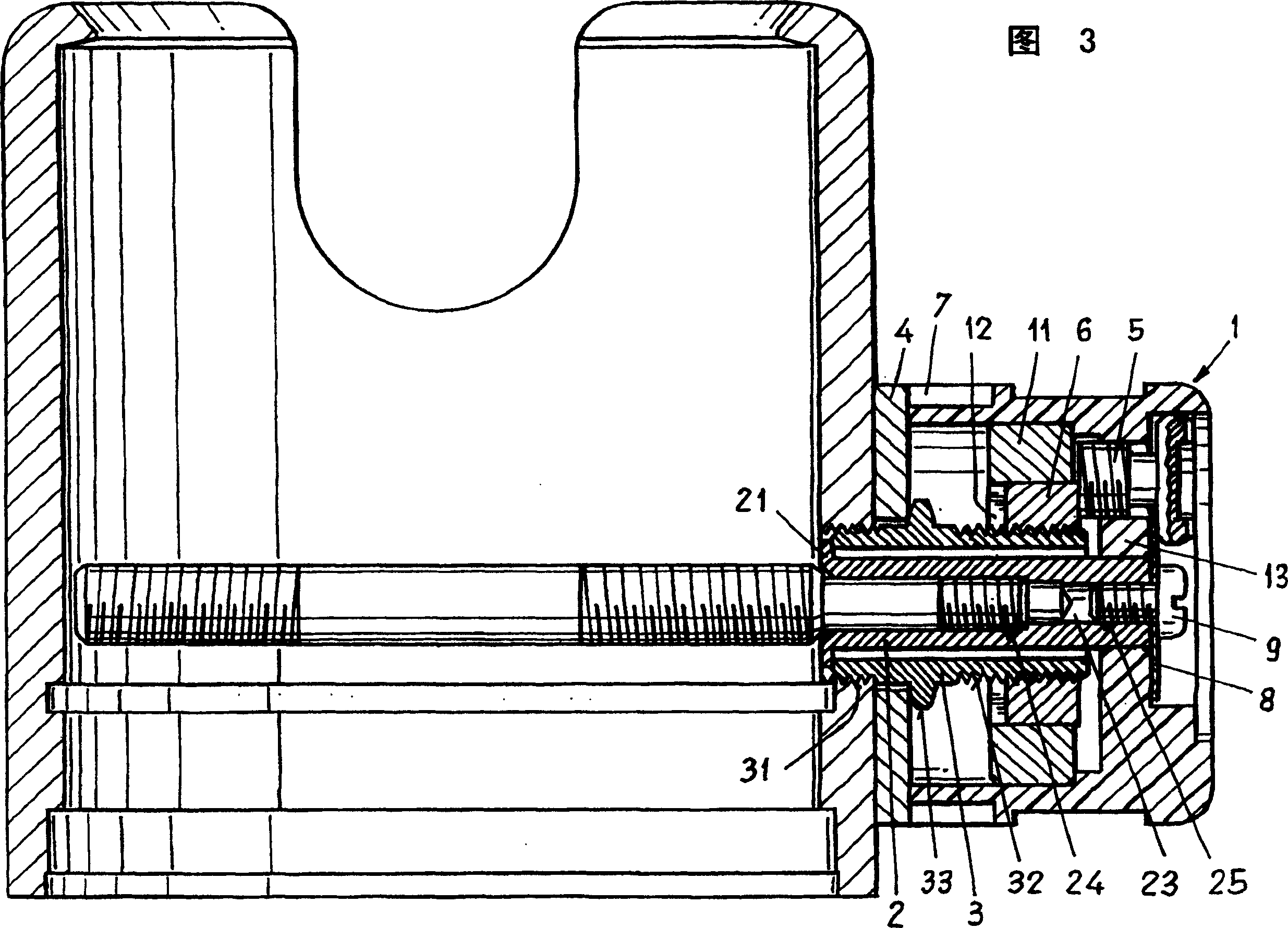
[0015] As shown in Figure 2, the knob includes a screw housing 1, a connecting piece that connects the screw housing 1 with the shaft, a sleeve 3, a cover 4, a screw 5 for adjusting the clamping force, and a The chuck 6, a ring scale 7 and a fixing screw to avoid missing components 8. The screw housing 1 is made of plastic or metal.

[0016] The screw housing 1 has a guide portion 11 with a hexagonal hole 12, which is fixed in the screw housing 1 and has a threaded hole in the bottom 13 of the housing. The connector 2 has a flange 21 at one end and a hexagonal portion 22 at the other end. It also has a through hole 23 with a first threaded section 24 and a second threaded section 25. The connecting piece 2 is screwed onto the shaft by the first threaded section 24. The sleeve 3 has a first threaded section 31, a second threaded section 32 and a hexagonal portion 33 and it is fixed to the housing by the first threaded section 31. The sleeve 3 surrounds the connector 2 and abuts aga...


PUM


Abstract

The rotatable knob contains a knob shell (1), a coupling part (2) for the connection of the knob shell to the spindle, a sleeve (3) which is connectable to the housing, a cover disc (4) which is secured by the sleeve to the housing, a screw (5) arranged in the knob shell for the setting of the holding force and a clamping disc (6) which cooperates with the knob shell and the sleeve so that, on rotation of knob shell, the clamping disc executes a relative movement and can be brought into engagement with the screw to restrict the rotation of the knob shell. For this purpose, the clamping disc is guided in the knob shell and is rotatably arranged on the sleeve so that, on rotation of the knob shell, the clamping disc executes a synchronous rotary movement with the knob shell and the linear movement with respect to the knob shell. The rotatable knob has the advantage that an overturning of the knob shell beyond the stop position is prevented by the synchronous rotary movement of the knob shell and the clamping disc and that the rotatable knob can be straightforwardly released by turning it in the opposite direction.

Description

Technical field [0001] The invention relates to a knob for fixing the bottom plate of an instrument. Background technique [0002] Figure 1 shows a known knob for fixing the instrument base plate in the housing by means of a fastening device with a shaft. The knob is installed on the housing and the shaft. The knob includes a screw housing 1 with internal threads, a connecting piece that connects the screw housing 1 to the shaft, a sleeve 3 that can be connected to the housing, and a sleeve 3 that is fixed on the housing. The cover plate 4, a screw 5 placed in the screw housing 1 and adjust the tightening force, and a chuck 6, the chuck has an external thread engaged with the internal thread of the screw housing, and is on the sleeve 3. Being guided in such a way that by rotating and screwing the housing 1, the chuck 6 completes the movement relative to the screwing housing 1. [0003] In order to fix the bottom plate of the instrument, turn the screw housing 1 clockwise. In this...

Claims


Application Information

Patent Timeline
Patent Type & Authority Patents(China)
IPC IPC(8): H05K7/00G12B9/04F16M11/00F16M11/06G05G1/10
CPCG05G1/10Y10T74/2084F16M11/06
Inventor 菲利普·沃格特
Owner PHILIP VOGT
Features
  • R&D
  • Intellectual Property
  • Life Sciences
  • Materials
  • Tech Scout
  • Unparalleled Data Quality
  • Higher Quality Content
  • 60% Fewer Hallucinations
Learn More