Cam-follower release mechanism for fiber optic modules with side delatching mechanisms

a technology of fiber optic modules and release mechanisms, applied in the field of fiber optic modules, can solve the problems of more difficult handling for users, more difficult to remove failed fiber optic modules, and inability to meet the needs of users,

Inactive Publication Date: 2005-02-08
LUMENTUM OPERATIONS LLC
View PDF281 Cites 142 Cited by
  • Summary
  • Abstract
  • Description
  • Claims
  • Application Information

AI Technical Summary

Benefits of technology

In another embodiment, a fiber optic module with a release mechanism includes a housing having a pair of pins in a bottom side, the housing further having one or more optical plug receptacles in a front side, an opening in a back side, and a pair of side openings forming a catch in each side, the catch in each side to receive a side tab in each side of a cage to retain the fiber optic module therein, the one or more optical plug receptacles to receive one or more fiber optic cable plugs; a printed circuit board mounted in the housing, the printed circuit board at one end including one or more electro-optic transducers to convert optical signals into electrical signals or electrical signals into optical signals, the printed circuit board at another end including an edge connection aligned with the opening in the back side of the housing to couple to a connector of a host, the printed circuit board further including one or more integrated circuits electrically coupled between the edge connection and the one or more electro-optic transducers; and a cam follower release mechanism movably coupled to the housing to release the fiber optic module from the cage using a rotational action. The cam follower release mechanism may include a rotatable lever including a cam portion at one end and an opening about which the cam portion may rotate; a fork including a base and a pair of pillars with a pair of side sliding actuators coupled respectively thereto, each of the pair of side sliding actuators including a delatching actuator, the base further including a bearing surface to support the cam portion of the rotatable lever, the pair of side sliding actuators to slide along the respective pair of side openings in the housing in response to rotation action of the rotatable lever and the delatching actuators to push out on the side tabs of the cage to release the fiber optic module there-from; and a pin coupled to one of the pair of pillars, the opening in the rotatable lever rotatably coupled over the pin, the pin to allow the rotatable lever to rotate between a first position and a second position to release the fiber optic module from the cage. The base of the release mechansim may further include a stop to limit the angle of rotation of the rotatable lever. The rotatable lever may include a pair of rotatable levers coupled together by a handlebar at a first end, each of the pair of rotatable levers includes the cam portion at a second end opposite the first end and the opening about which the cam portion may rotate. The cam release mechanism may further include a leaf spring coupled between the base and the housing to moveably couple the cam release mechanism to the housing and to return the rotatable lever to the first position.
In yet another embodiment, the fiber optic module with the release mechanism includes a printed circuit board, a housing around the printed circuit board, and the release mechanism moveably coupled to the front side of the housing between a latch position and a release position. The printed circuit board has one or more opto-electronic devices at one end, an edge connection at an opposite end, and one or more integrated circuits electrically coupled between the edge connection and the one or more opto-electronic devices. The housing has a top side, a bottom side, a right side and a left side, with one or more optical plug receptacles in the front side to receive one or more optical plugs of a fiber optic cable in alignment with the one or more optoelectronic devices, and a pair of openings forming catches in the right side and the left side. The catches in the right side and the left side of the housing can engage tabs in a right side and a left side of a cage to retain the fiber optic module therein. The release mechanism moves from the latch position to the release position using a rotational action to release the fiber optic module from the cage. The release mechanism includes a rotational cam mechanism and a follower mechanism moveably coupled to the rotational cam mechanism. The rotational cam mechanism receives the rotational action. The rotational cam mechanism includes a rotatable cam portion and a rotatable lever portion. The rotatable cam portion of the rotational cam mechanism is moveably coupled to the front side of the housing. The follower mechanism moveably couples to the rotational cam mechanism to translate its rotational action into a linear action. The follower mechanism includes a pair of delatch actuators each having a ramp. The ramps in the pair of pair of delatch actuators release the tabs of the right side and the left side of the cage from the catches in the right side and left side of the housing by pushing out away from the sides of the fiber optic module and release it from the cage. This is in response to the linear action of the follower mechanism translated from the rotational action of the rotational cam mechanism. The release mechanism further includes a spring mechanism coupled between the release mechanism and the housing, the spring mechanism to generate tension between the housing and the release mechanism to return the release mechanism to the latch position such that the tabs of the cage can engage the catches of the fiber optic module. The rotatable cam portion may be an elliptical cam lobe and the spring mechanism may be a leaf type spring. The follower mechanism may be a fork including a pair of side slide actuators respectively with the pair of delatch actuators.

Problems solved by technology

However, the smaller form factor makes it more difficult for a user to handle.
While plugging in a new fiber optic module is usually easy, it is more difficult to remove the failed fiber optic module because of other components surrounding it.
Additionally, a user should not attempt to pull on fiber optic cables in order to try and remove a failed fiber optic module or else the user might cause damage thereto.
It has been determined that this method is not very reliable with users complaining of the difficulty in removing pluggable fiber optic modules in this manner.
Users often complain that traditional methods offer little leverage in getting a sufficient grip on the module when attempting to pull it out of a module receptacle.
Another complaint is that traditional actuators used to remove fiber optic modules are inaccessible or invisible.
Other users complain that once released by the traditional method, it is difficult to withdraw the fiber optic module out of its cage or module receptacle.
Additionally, the pushing and then pulling of traditional methods places extra strain on components of the fiber optic module itself, the cage assembly or module receptacle and any electrical connections which the fiber optic module makes with an electrical connector.

Method used


Image

  • Cam-follower release mechanism for fiber optic modules with side delatching mechanisms
  • Cam-follower release mechanism for fiber optic modules with side delatching mechanisms
  • Cam-follower release mechanism for fiber optic modules with side delatching mechanisms

Examples


Embodiment Construction

In the following detailed description of the invention, numerous specific details are set forth in order to provide a thorough understanding of the invention. However, one skilled in the art would recognize that the invention may be practiced without these specific details. In other instances well known methods, procedures, components, and circuits have not been described in detail so as not to unnecessarily obscure aspects of the invention.

In the following description, certain terminology is used to describe various features of the invention. For example, a “fiber-optic transceiver” is a fiber optic module having optical signal transmit and receive capability. The terms “disengage”, “release”, “unlatch”, and “de-latch” may be used interchangeably when referring to the de-coupling of a fiber optic module from a cage assembly.

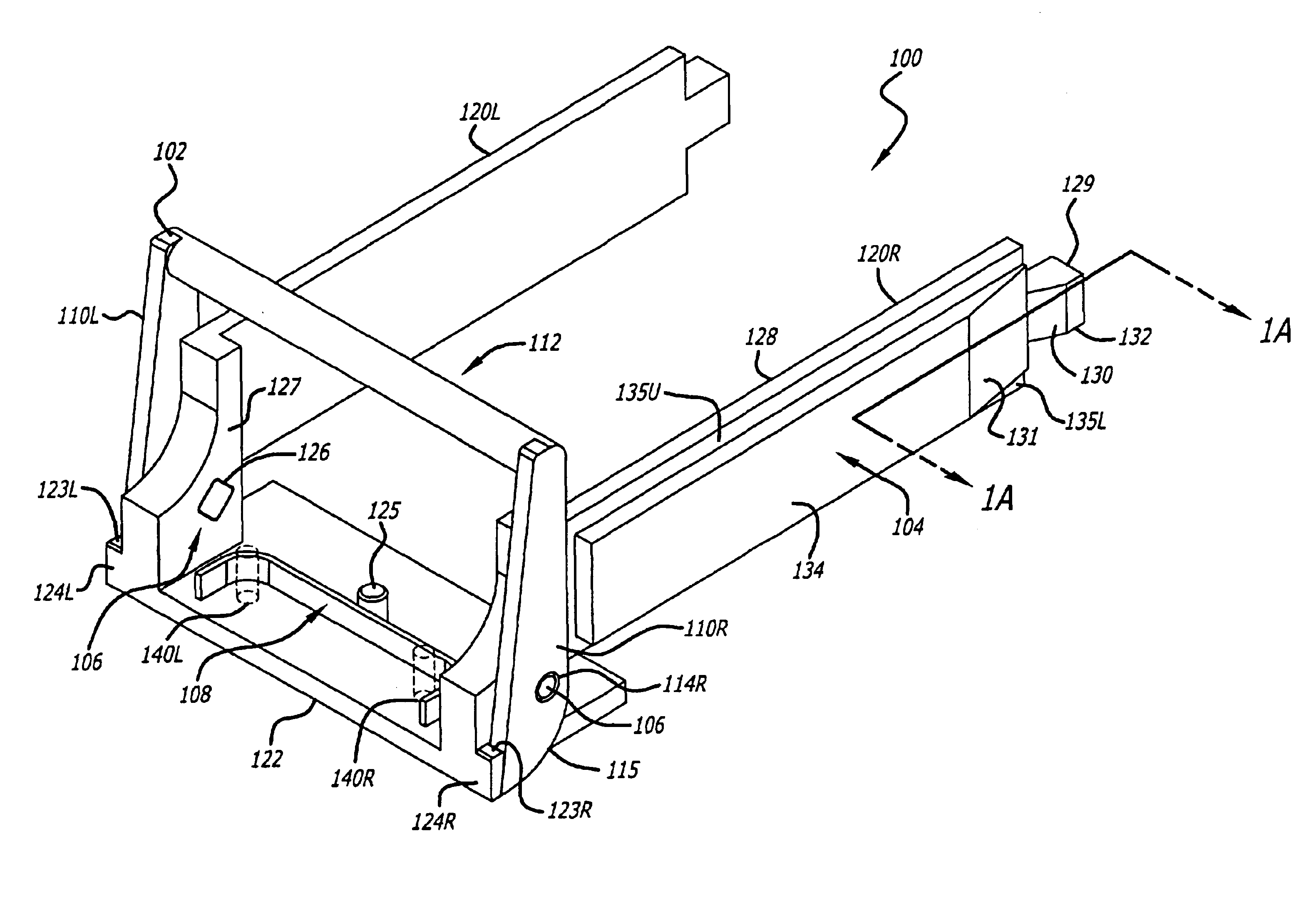
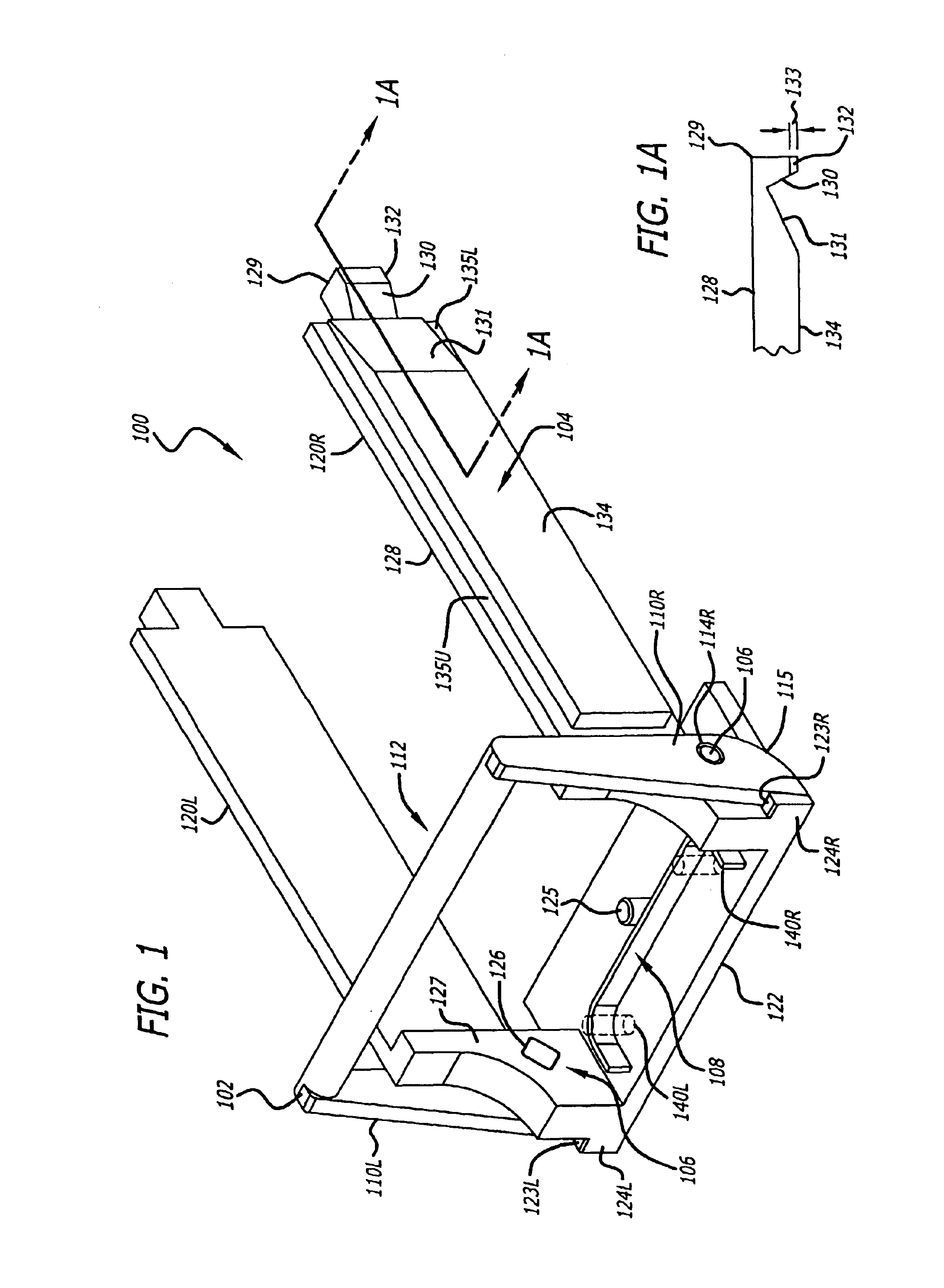
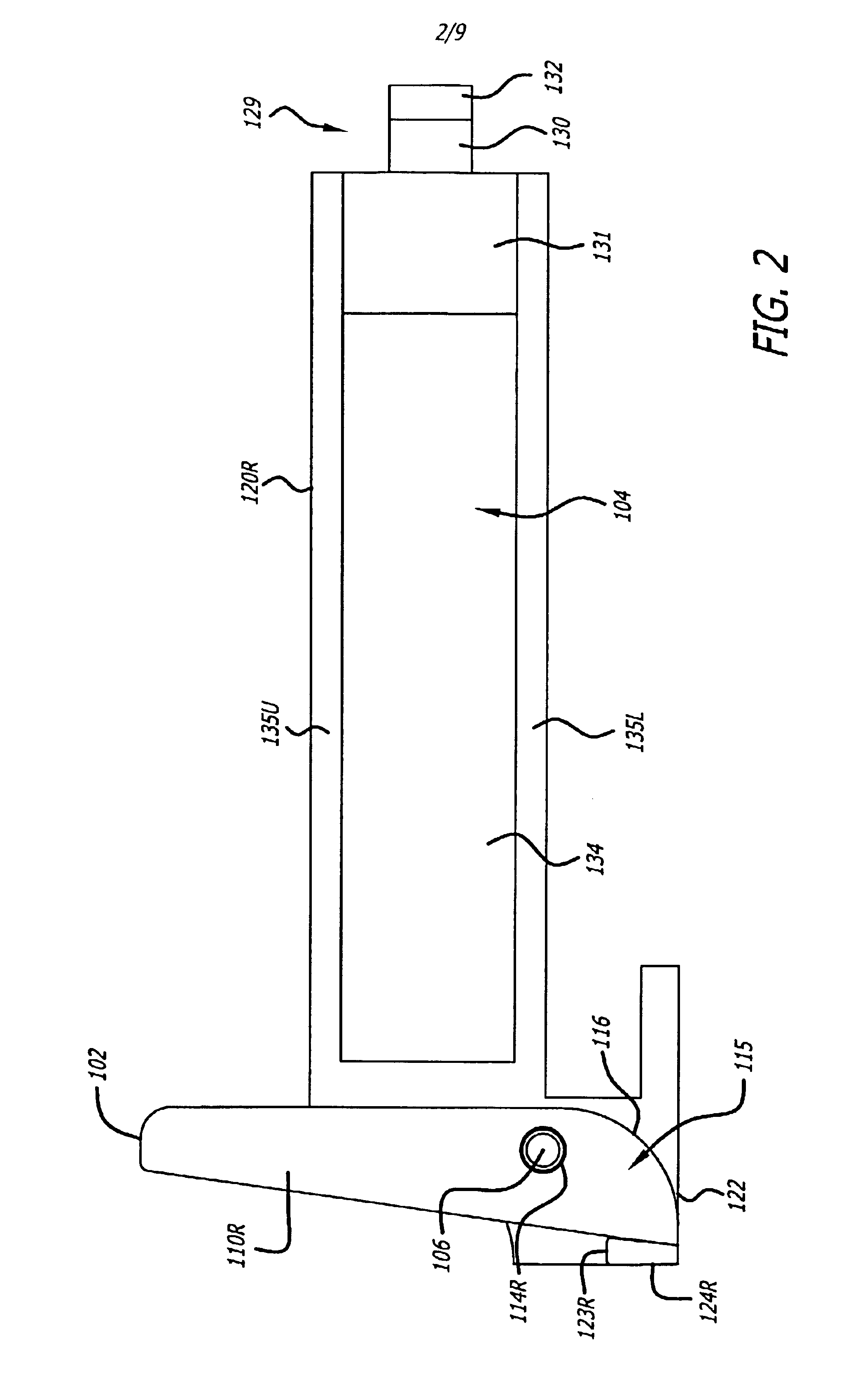
The invention includes methods, apparatuses and systems for fiber optic modules including releasable fiber optic modules in a form factor to satisfy a 10 Gigabi...


PUM


Abstract

A cam-follower release mechanism for fiber optic modules with side releases. The cam-follower release mechanism translates rotational motion into linear motion. The release mechanism has a rotatable bail lever with a cam lobe that pivots about a pivot point and presses against a bearing surface of the fiber optic module. The release mechanism further has a base with a pin about with the rotatable bail lever may pivot and a sliding fork with sliding side actuators and delatch actuators at each end. As a follower, the base and sliding fork is linearly pulled as the rotatable bail lever is rotated. As the sliding fork is pulled out, the delatch actuators at each end push in on side tabs of a cage into which the fiber optic module may be inserted. The release mechanism further has a spring to apply a force against the rotation of the rotatable bail lever to return it to home and retain the release mechanism moveable coupled to the fiber optic module. The fiber optic module further includes opto-electronic devices mounted to a printed circuit board, and a housing.

Description

FIELDThis invention relates generally to fiber optic modules. More particularly, the invention relates to retention and release mechanisms for unplugging fiber optic modules.BACKGROUNDFiber optic modules can transduce electrical data signals in order to transmit optical signals over optical fibers. Fiber optic modules can also transduce optical signals received over optical fibers into electrical data signals.The size or form factor of fiber optic modules is important. The smaller the form factor of a fiber optic module, the less space taken on a printed circuit board to which it couples. A smaller form factor allows a greater number of fiber optic modules to be coupled onto a printed circuit board to support additional communication channels. However, the smaller form factor makes it more difficult for a user to handle.When a fiber optic module embedded in a system fails it is desirable to replace it, particularly when other communication channels are supported by other operating f...

Claims


Application Information

Patent Timeline
Patent Type & Authority Patents(United States)
IPC IPC(8): G02B6/38G02B6/42H01R13/46
CPCG02B6/3825G02B6/4292G02B6/3897G02B6/3893G02B6/4246G02B6/4261G02B6/36
Inventor PANG, RON CHENG CHUANTAN, KEE-SINPHANG, KAH YUAN
Owner LUMENTUM OPERATIONS LLC
Why Eureka
Try Eureka