Main shaft motor

A technology of spindle motor and motor, applied in the direction of casing/housing/support, instrument, recording information storage, etc., can solve the problems of resin cracking, loose installation, large difference in thermal expansion rate of resin and metal, etc.

Inactive Publication Date: 2006-08-09
TOKYO PARTS IND CO LTD
View PDF0 Cites 1 Cited by
  • Summary
  • Abstract
  • Description
  • Claims
  • Application Information

AI Technical Summary

Problems solved by technology

However, its disadvantage is that the thermal expansion rate of resin and metal is greatly different due to the influence of temperature changes after that, so it cannot adapt to the processing size and installation size in the welding part and the installation hole, and between the installation holes. Changes, resulting in loose installation and resin cracking and other phenomena
In addition, its processing is complicated, assembly time is labor-intensive, and the cost is high

Method used


Image

  • Main shaft motor
  • Main shaft motor
  • Main shaft motor

Examples


Embodiment Construction

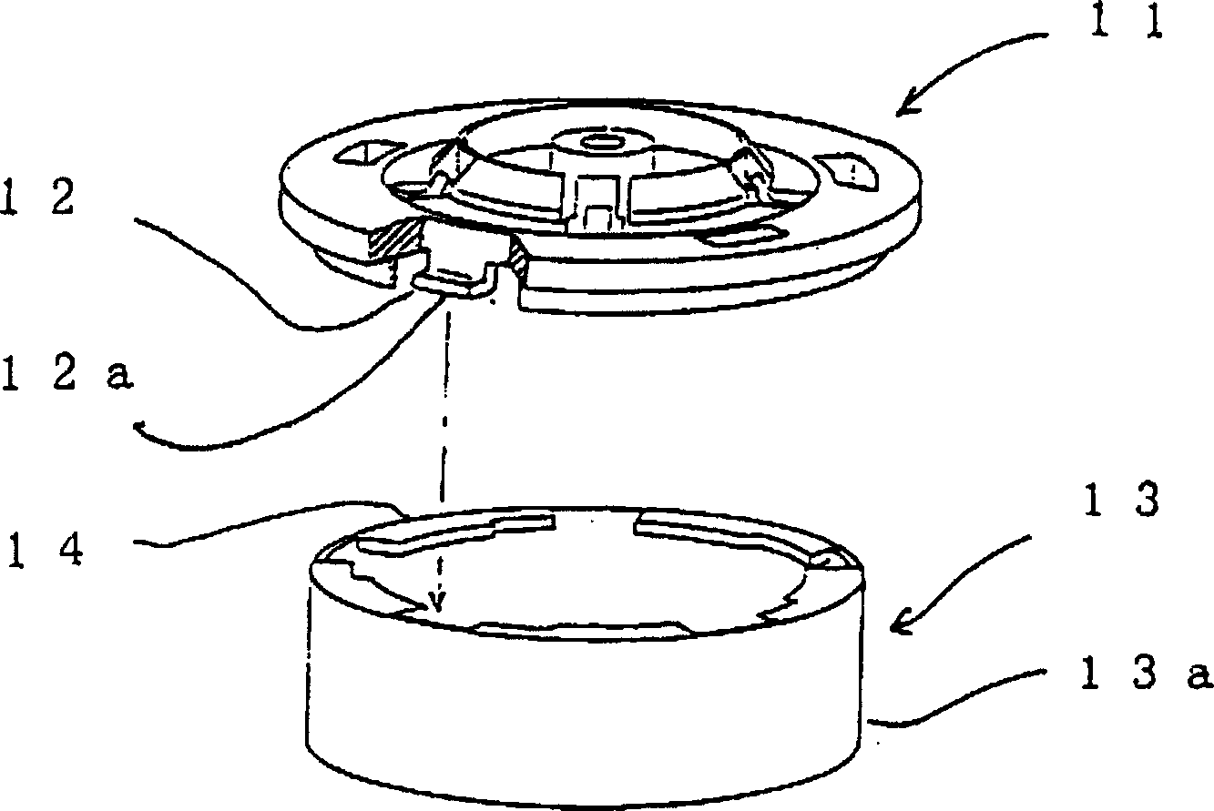
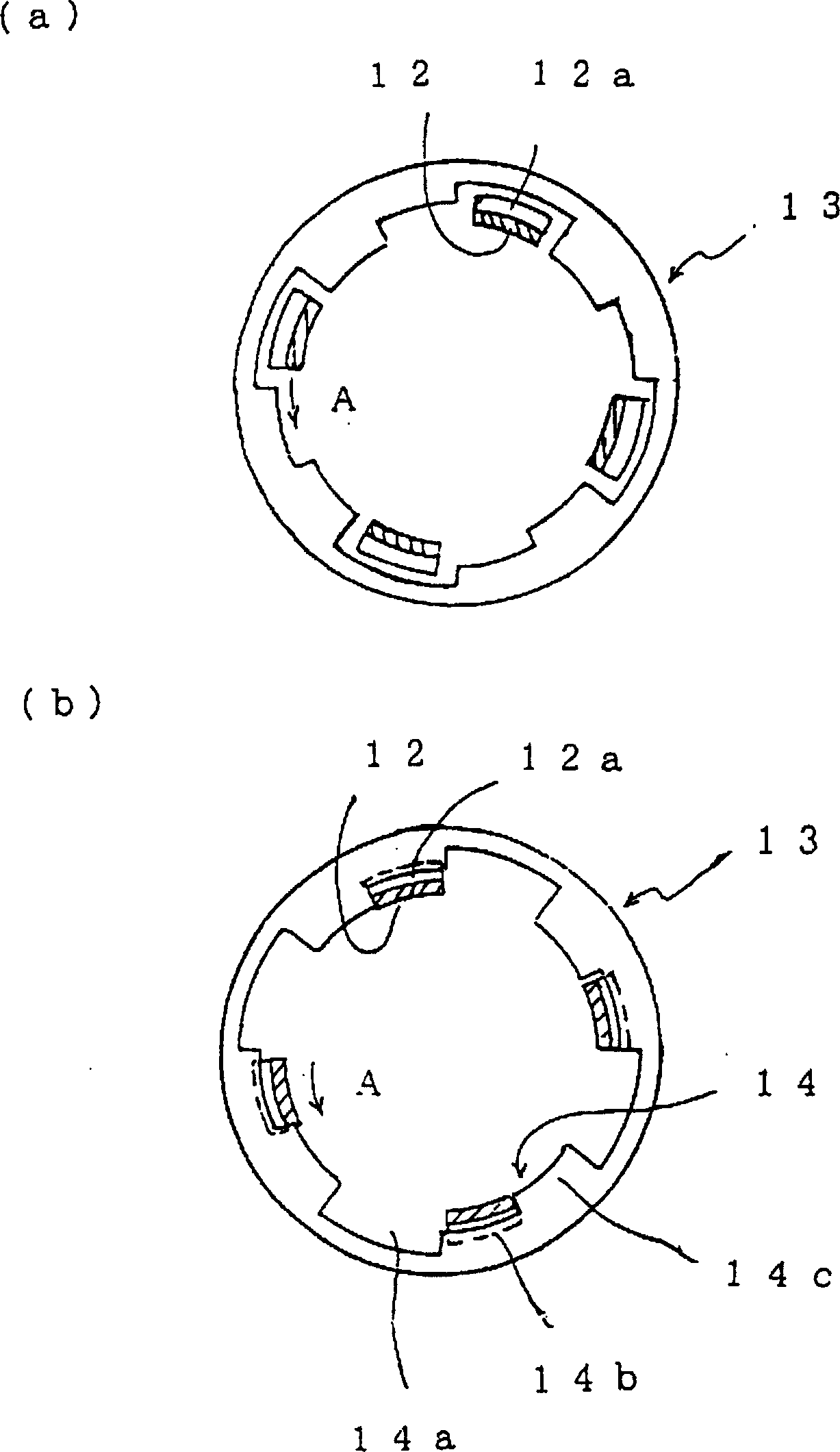
[0014] Hereinafter, a first embodiment of the present invention will be described in detail with reference to the drawings. figure 1 It is an exploded perspective view showing the main part of the first embodiment of the present invention. figure 2 (a), (b) means to put figure 1 Schematic diagram of the configuration in which the turntable is fixed to the motor housing.

[0015] exist Figure 1 ~ Figure 2 Among them, 11 is a turntable of the spindle motor, and 12 is an elastic claw for fixing, and in this embodiment, an example in which four are arranged at approximately 90-degree intervals is shown. But if there are more than 2, they can be properly arranged. 12a is a front end portion of the claw, which is formed by bending the front end of the fixing claw 12 outward in a substantially L-shape. Reference numeral 13 denotes a motor housing, which has a short cylindrical tube portion 13 a and a flange-shaped fitting portion 14 extending from one end of the tube portion ...


PUM


Abstract

The present invention provides one main shaft motor and simple method of fixing turntable and motor casing reliably. On the turntable, there are elastic claws with L-shaped end, notches for inserting the claws to the casing, and embedding parts connected to the notches for embedding the claws. After the claws are inserted into the notches, the turntable and the motor casing are made to form one integral through rotation.

Description

technical field [0001] The present invention relates to a spindle motor, and more specifically relates to a spindle motor with an integrated structure, which includes: a turntable for placing and rotating a magnetic disk or an optical disk, and a motor housing of the spindle motor. Background technique [0002] In the past, the recommended product of the spindle motor for rotating optical discs such as CD-ROMs was a spindle motor with an integrated structure of a turntable and a motor housing. Use below Figure 4 To illustrate. [0003] Figure 4 It is a schematic diagram illustrating the integration of the turntable and the motor housing in the conventional spindle motor. Figure 4 Omit parts that are not needed in the assembly. 1 is a turntable formed integrally with resin or the like and having a center hole. 2 is a boss for installation provided on the installation surface of the turntable 1 . [0004] 3 is an inverted cup-shaped motor housing with a central hole form...

Claims


Application Information

Patent Timeline
Patent Type & Authority Patents(China)
IPC IPC(8): H02K5/00G11B17/00
Inventor 岸勇祐
Owner TOKYO PARTS IND CO LTD
Why Eureka
Try Eureka