Optical positioning system and method for computing this optical positioning system moving value

A technology of optical positioning and moving values, which is applied in the direction of calculation, using optical devices, and using optical devices to transmit sensing components, etc., to achieve the effect of wide use value and increased operation speed

Inactive Publication Date: 2006-11-08
INTELLECTUAL DISCOVERY CO LTD
View PDF2 Cites 0 Cited by
  • Summary
  • Abstract
  • Description
  • Claims
  • Application Information

AI Technical Summary

Problems solved by technology

In order to solve the defects of the optical positioning system and the method of calculating the movement value of the optical positioning system, the relevant manufacturers have tried their best to find a solution, but no applicable design has been developed for a long time. This is obviously the urgent desire of the relevant industry solved problem

Method used


Image

  • Optical positioning system and method for computing this optical positioning system moving value
  • Optical positioning system and method for computing this optical positioning system moving value
  • Optical positioning system and method for computing this optical positioning system moving value

Examples


Embodiment Construction

[0033] The optical positioning system according to the present invention and the method for calculating the movement value of the optical positioning system will be described in detail below with reference to the accompanying drawings and preferred embodiments.

[0034]In the following the invention will be described more fully with reference to the accompanying drawings, in which preferred embodiments of the invention are shown. However, the invention may be embodied in different forms and should not be construed as limited to the embodiments set forth herein. These embodiments are presented so that this disclosure will be thorough and complete, and will fully convey the scope of the invention to those skilled in the art. Like reference numerals refer to like parts throughout the specification.

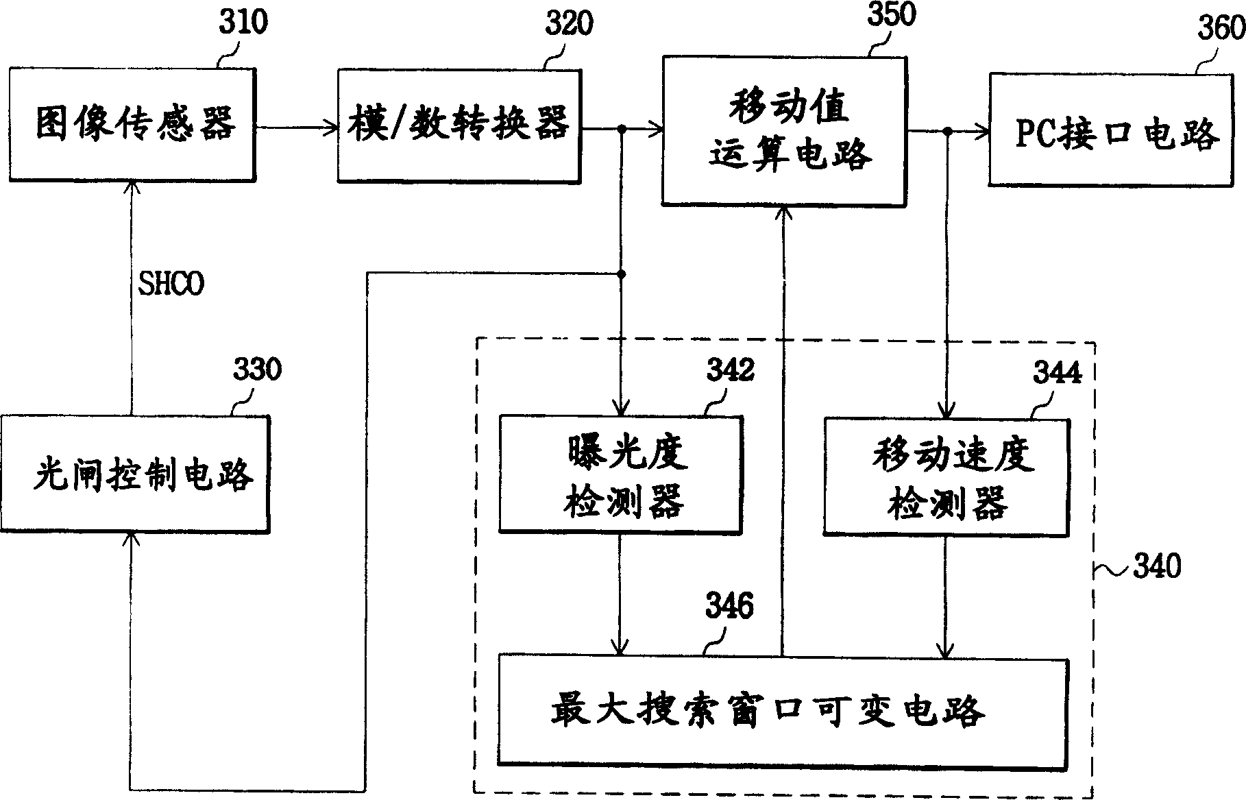
[0035] see image 3 Shown is a block diagram illustrating the sensor circuit of the first embodiment of the optical positioning system according to the present invention. The sens...


PUM


Abstract

The present invention relates to an optical positioning system and a method for calculating the movement value of the optical positioning system, which is composed of: an image sensor for detecting light reflected from the surface of the workbench and generating an image signal; a maximum search window can be a change circuit for inputting at least one of an image signal and a shift value to change the size of the maximum search window; and a shift value calculation circuit for calculating the shift value of the image signal using the size-changed maximum search window . Therefore, by calculating the movement value according to at least one of a luminous flux and a movement speed, changing at least one maximum search window and a sampling rate can obtain an accurate movement value.

Description

technical field [0001] The present invention relates to an optical positioning system, in particular to an optical positioning system capable of adaptively changing the maximum search window and / or sampling rate according to the luminous flux and moving speed of incident light and a method for calculating its moving value. [0002] This application claims priority to Korean Patent Application No. 2002-72821 filed on November 21, 2002 and Korean Patent No. 2003-79623 filed on November 11, 2003, the disclosures of which are hereby incorporated by reference in their entirety. Background technique [0003] like figure 1 As shown, a common optical positioning system is composed of a light source 8, a lens 5, and an image sensor of the sensor circuit 3 (not shown in the figure). [0004] exist figure 1 Among them, the number 2 represents the table surface, and the numbers 4, 6, and 7 represent the light. [0005] exist figure 1 In the optical positioning system shown, light 7 ...

Claims


Application Information

Patent Timeline
Patent Type & Authority Patents(China)
IPC IPC(8): G06F3/033G01B11/04G01D5/26
CPCG01D5/26
Inventor 郭钟择
Owner INTELLECTUAL DISCOVERY CO LTD
Why Eureka
Try Eureka