Chromatographic separatory

A technology for chromatographic separation and switching devices, which is applied in the field of chromatographic separation devices, can solve the problems of expensive chromatographic separation devices, and achieve the effect of reducing pressure specifications

Inactive Publication Date: 2006-11-29
ORGANO CORP
View PDF0 Cites 0 Cited by
  • Summary
  • Abstract
  • Description
  • Claims
  • Application Information

AI Technical Summary

Problems solved by technology

Due to the use of columns and pumps with such pressure specifications, the price of chromatographic separation equipment is more expensive

Method used


Image

  • Chromatographic separatory
  • Chromatographic separatory
  • Chromatographic separatory

Examples


Embodiment

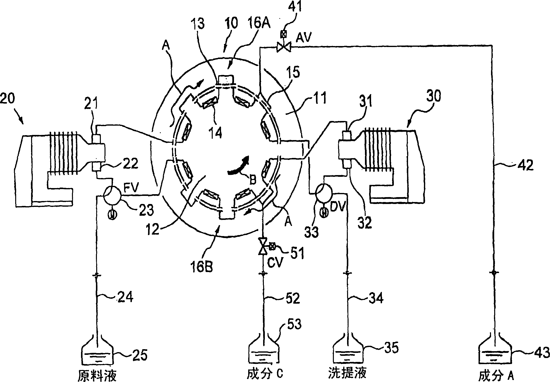
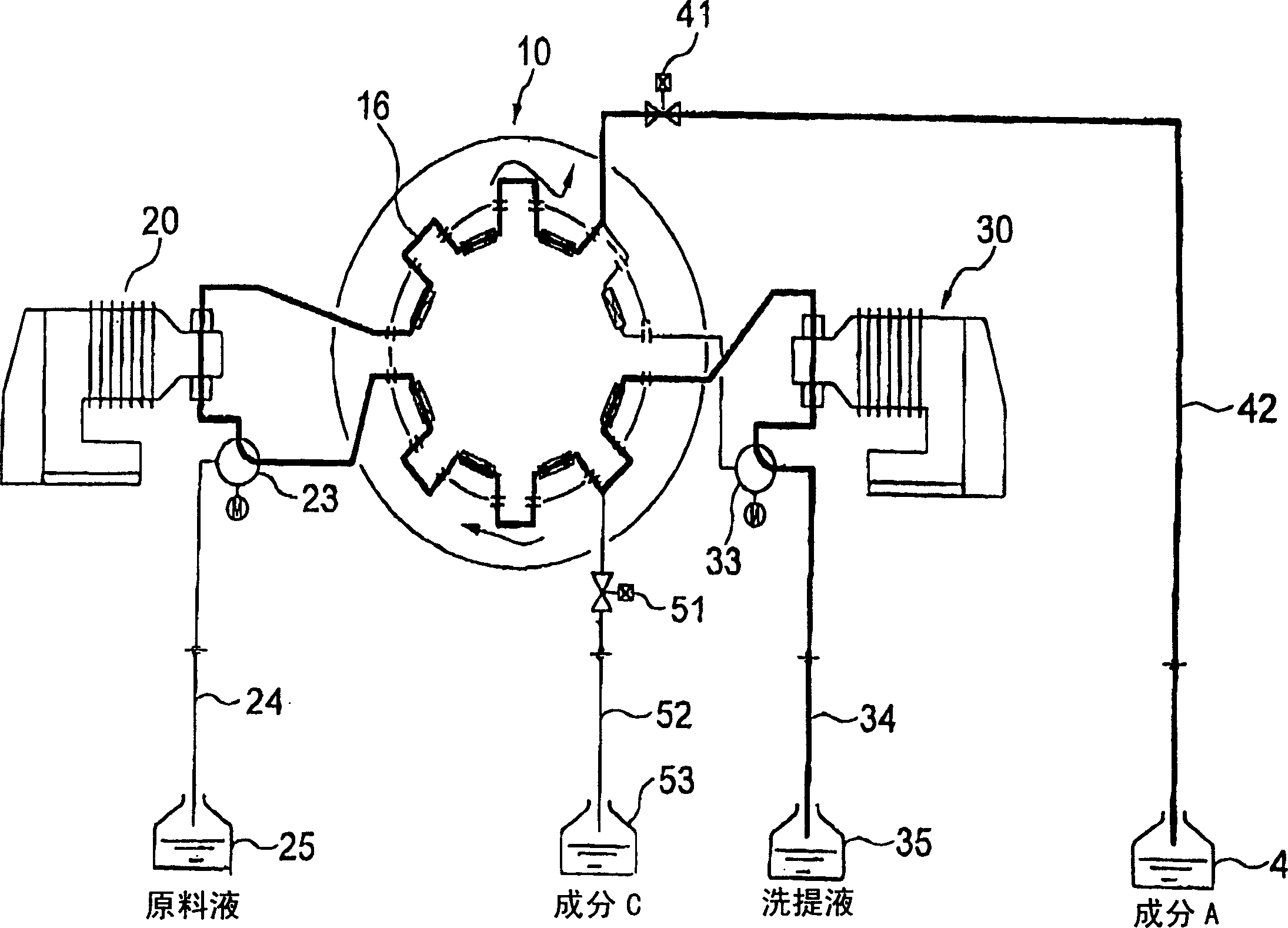
[0025] Embodiments of the present invention will be described in detail below with reference to the drawings. figure 1 It is a model block diagram of the intermittent moving layer chromatography separation device (hereinafter referred to as the separation device) in the embodiment of the present invention. This separation device has two pumps 20, 30, and is provided with a switch to select any one of the circulation mode in which each pump is inserted into the circulation path and the liquid injection mode connected to the liquid injection pipe on the suction port of each pump. Valve 23, 33.

[0026] In this separation device, in one process, by selecting the first and second switching valves 23, 33 to the circulation mode, the eight columns 14 filled with adsorbent pass through the nozzles 13 of the rotary valve 10 and the first and second pumps. 20 and 30 form a circulation path 16 connected in a circular shape. The liquid flow in the circulation path 16 is in the directi...


PUM


Abstract

A chromatographic separator which circulates a raw material liquid having at least two components and an eluate through a circulating path (16) consisting of endlessly connected columns (14) to separate the raw material liquid into two components. Switching between switching valves (23, 33) allows pumps (20, 30) to be used both for liquid circulation through the circulating path (16) and for liquids flow-in from respective storage tanks (25, 35). On-off valves are used for draining valves (41, 51) for respective liquids to lower the pressure specifications of the circulating path (16).

Description

technical field [0001] The present invention relates to a chromatographic separation device, more specifically, to a control system for a circulation path and a pump in an intermittent moving layer chromatographic separation device and a simulated moving layer chromatographic separation device. Background technique [0002] Chromatographic separation equipment is widely used for the purpose of extracting one or more components from a raw material fluid composed of many components obtained by natural or chemical reactions in the sugar and pharmaceutical industries. In chromatographic separation apparatuses, various moving-bed apparatuses have recently been proposed in addition to the conventionally used intermittent fixed-layer apparatuses. [0003] Figure 8 It is a cross-sectional schematic diagram of a column showing the principle of a general moving layer system chromatographic separation device. In the column 60, a prepack (adsorbent) 62 is packed, which is filled with ...

Claims


Application Information

Patent Timeline
Patent Type & Authority Patents(China)
IPC IPC(8): G01N30/46G01N30/32B01D15/00B01D15/08B01D15/18G01N30/26G01N30/88
CPCB01D15/1842B01D2215/023G01N30/46
Inventor 小川裕路佐藤康平
Owner ORGANO CORP
Why Eureka
Try Eureka